High-strength synthetic resin tile

A synthetic resin and high-strength technology, which is applied to roofs, roofs, buildings, etc. that use tiles/slate tiles, can solve problems such as poor stability, single structure of synthetic resin tiles, and unoptimized safety performance, and achieve convenient splicing and Demolition, sound insulation and fire barriers to improve and reinforce the effect of penetration protection

Inactive Publication Date: 2018-09-28
赣州恒利建材有限公司
7 Cites 0 Cited by

AI-Extracted Technical Summary

Problems solved by technology

[0003] However, the existing synthetic resin tiles have a single structure, are stacked in layers in terms of installation, and have poor stability. At the same time, water seepage is prone t...

Abstract

The invention discloses a high-strength synthetic resin tile comprising a first tile body and a second tile body. Alignment rods are fixedly connected to the two ends of the outer side of the first tile body and the two ends of the outer side of the second tile body, an alignment plate is arranged on the surfaces of the alignment rods, alignment grooves are formed in both ends of the interior of the alignment plate, and the inner sides of the alignment grooves are slidably sleeved with the surfaces of the alignment rods. The alignment rods are internally provided with grooves, first springs are fixedly connected to the inner sides of the grooves, clamping pins are fixedly connected to the other ends of the first springs, through holes communicate with the interiors of the alignment grooves, and the inner sides of the through holes are slidably sleeved with the surfaces of the clamping pins. According to the high-strength synthetic resin tile, splicing and disassembly of the two tile bodies are facilitated, at the same time, the joint of the two tile bodies can be strengthened to prevent from permeation, and moreover, a sound insulation layer and a fireproof layer are added so as toimprove the practicability of the tile.

Application Domain

Roof covering using tiles/slates

Technology Topic

EngineeringHigh intensity +2

Image

  • High-strength synthetic resin tile
  • High-strength synthetic resin tile
  • High-strength synthetic resin tile

Examples

  • Experimental program(1)

Example Embodiment

[0020] The technical solutions in the embodiments of the present invention will be clearly and completely described below in conjunction with the accompanying drawings in the embodiments of the present invention. Obviously, the described embodiments are only a part of the embodiments of the present invention, rather than all the embodiments. Based on the embodiments of the present invention, all other embodiments obtained by those of ordinary skill in the art without creative work shall fall within the protection scope of the present invention.
[0021] In the description of the present invention, it should be understood that the terms "longitudinal", "lateral", "upper", "lower", "front", "rear", "left", "right", "vertical", The orientation or positional relationship indicated by "horizontal", "top", "bottom", "inner", "outer", etc. are based on the orientation or positional relationship shown in the drawings, and are only for the convenience of describing the present invention, rather than indicating or It is implied that the device or element referred to must have a specific orientation, be configured and operated in a specific orientation, and therefore cannot be understood as a limitation to the present invention.
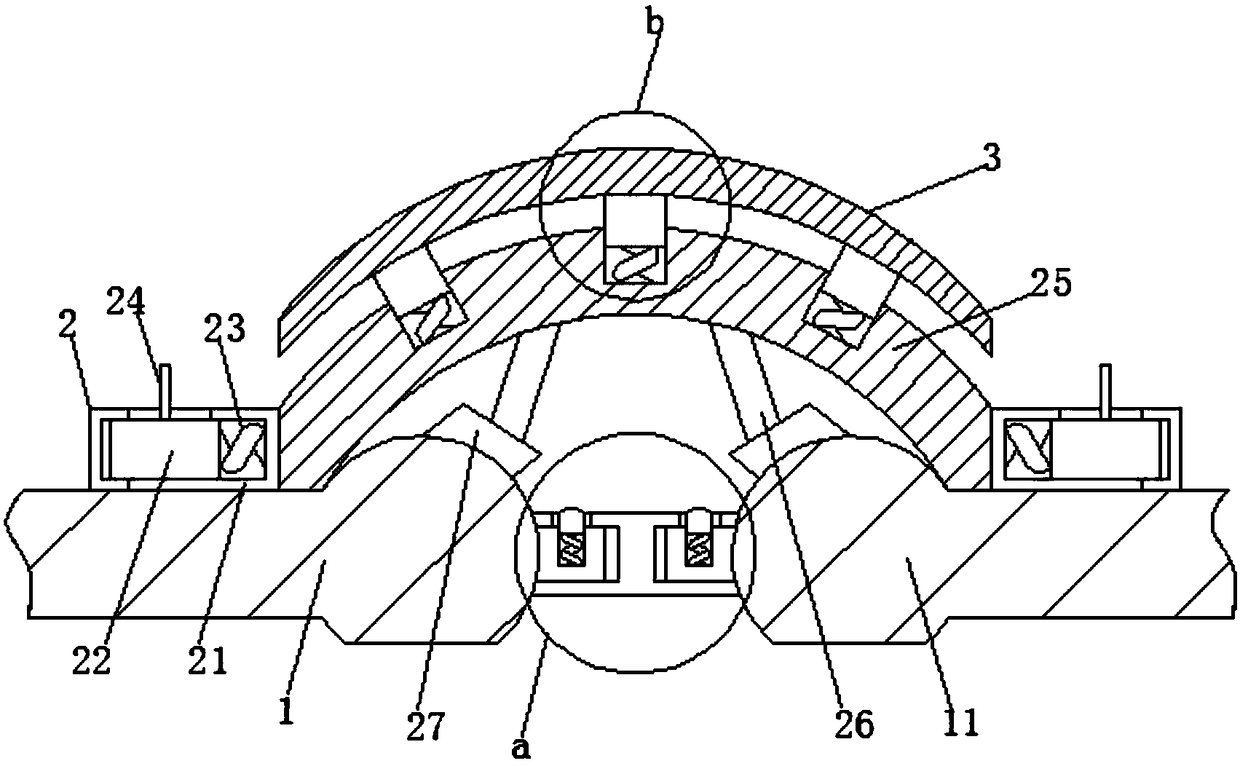
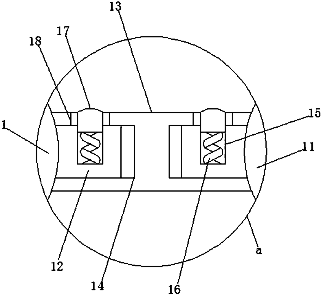
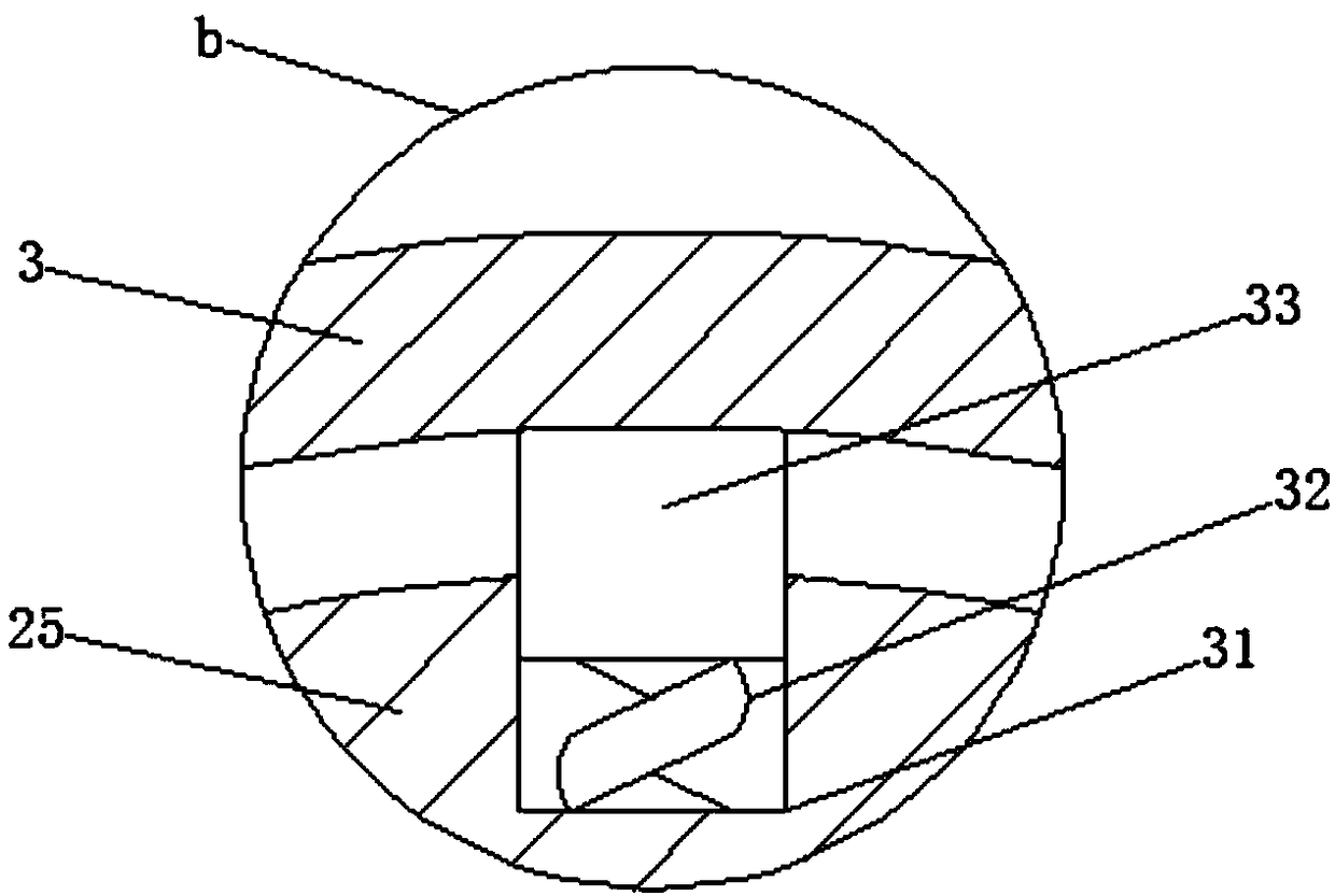
[0022] See Figure 1-4 , The present invention provides a technical solution: a high-strength synthetic resin tile, including a first tile 1 and a second tile 11, the outer ends of the first tile 1 and the outer two tiles 11 Both ends are fixedly connected with an alignment rod 12, the surface of the alignment rod 12 is provided with an alignment plate 13, and the inner ends of the alignment plate 13 are provided with alignment grooves 14, and the surface of the alignment rod 12 is slidingly sleeved and aligned. Inside the groove 14, the alignment rod 12 is provided with a groove 15, the inside of the groove 15 is fixedly connected with a first spring 16, the other end of the first spring 16 is fixedly connected with a bayonet pin 17, and the inside of the alignment groove 14 Connected with a through hole 18, the surface of the bayonet 17 slides through the inside of the hole 18 to facilitate the splicing of the two tiles. Both sides of the upper surface of the first tile 1 and the upper surface of the second tile 11 are both The socket 2 is fixedly connected. The upper surface of the first tile 1 and the upper surface of the second tile 11 are both closely attached to a fork seat 21. The outer end of the fork seat 21 is fixedly connected with an arc plate 25, and the fork seat A second spring 23 is fixedly connected to the inside of 21, a fork block 22 is fixedly connected to the other end of the second spring 23, a fork piece 24 is fixedly connected to the outside of the fork block 22, and the other end of the fork block 22 is slidingly sleeved The inner side of the socket 2 and the inner ends of the arc-shaped plate 25 are fixedly connected with a reinforcing rod 26, and the other end of the reinforcing rod 26 is fixedly connected with an arc-shaped block 27, which can fix the arc-shaped plate 25 and at the same time. 25 is reinforced from the inside. The surface of the first tile 1 and the surface of the second tile 11 are respectively close to the inside of the corresponding arc-shaped block 27, and the inside of the arc-shaped plate 25 is evenly distributed with buffer grooves 31 to buffer The inside of the groove 31 is fixedly connected with a third spring 32, the other end of the third spring 32 is fixedly connected with a buffer block 33, and the other end of the buffer block 33 is fixedly connected with a buffer plate 3, which can make the arc plate 25 impact on the outside. To achieve a buffer protection effect, the internal structure of the first tile 1 is the same as the internal structure of the second tile 11. The interior of the first tile 1 is provided with a first outer layer 4, a waterproof layer 41, a fireproof layer 42, The polyvinyl chloride layer 43, the polypropylene layer 44, the sound insulation layer 45, the corrosion-resistant layer 46, the moisture-proof layer 47 and the second outer layer 48. One side of the first outer layer 4 is adhered to the waterproof layer 41 and the other of the waterproof layer 41 A fireproof layer 42 is adhered to the side. The first outer layer 4 is made of glass fiber material, the waterproof layer 41 is made of polyethylene material, and the fireproof layer 42 is made of Portland cement, magnesium hydroxide or other inorganic high-temperature adhesives. The base material is composed of expanded perlite, mineral wool and other aggregates, other chemical additives, and water. The other side of the fireproof layer 42 is glued with a polyvinyl chloride layer 43, and the other side of the polyvinyl chloride layer 43 is glued. There is a polypropylene layer 44, the other side of the polypropylene layer 44 is bonded with a sound insulation layer 45 through composite adhesive, the sound insulation layer 45 is made of sound insulation felt material, and the other side of the sound insulation layer 45 is bonded with a corrosion-resistant layer 46, a corrosion-resistant layer The other side of 46 is glued with a moisture-proof layer 47, and the other side of the moisture-proof layer 47 is glued with a second outer layer 48. The corrosion-resistant layer 46 is composed of fluorine-containing ethylene polymer, and the moisture-proof layer 47 is coated with polyester material. , The second outer layer 48 The material composition of is the same as that of the first outer layer 4, which can improve the overall practicability of the tile.
[0023] In the specific implementation of the present invention: when two tiles need to be fixed, the positioning rod 12 outside the two tiles is inserted into the positioning slot 14 of the positioning plate 13, and then the two tiles can be Positioning, when the position of the bayonet 17 corresponds to the position of the through hole 18, the first spring 16 is compressed and reset so that the bayonet 17 can spring into the inside of the through hole 18 to complete the fixing of the two tiles. When the arc plate 25 needs to be fixed, the fork seats 21 on both sides of the arc plate 25 are respectively corresponding to the upper surfaces of the two tiles, and the fork piece 24 is moved so that the fork block 22 can enter the socket 2 When the position of the fork block 22 corresponds to the position of the socket 2, loosen the fork piece 24 so that the fork block 22 can be inserted into the inside of the socket 2 to complete the fixation of the arc plate 25. 26 cooperates with the arc block 27 to support the inner side of the arc plate 25. When the outer side of the arc plate 25 needs to be buffered, the third spring 32 is compressed and reset, so that the arc plate 25 is impacted by a heavy object. A shock absorption effect can be achieved by the buffer plate 3. The first outer layer 4, the waterproof layer 41 and the fireproof layer 42 are used as peripheral parts to protect against external collisions, rain and fire. The polyvinyl chloride layer 43, The polypropylene layer 44 and the sound insulation layer 45 are used as the middle structure. The polyvinyl chloride layer 43 and the polyethylene layer 44 can make the overall tile have sufficient hardness and toughness. The sound insulation layer 45 can play a sound insulation effect. The corrosion-resistant layer 46 and moisture-proof The layer 47 and the second outer layer 48 serve as internal parts, which can protect the entire tile from corrosion and moisture against the gas or moisture in the house.
[0024] Although the embodiments of the present invention have been shown and described, those of ordinary skill in the art can understand that various changes, modifications, and substitutions can be made to these embodiments without departing from the principle and spirit of the present invention. And variations, the scope of the present invention is defined by the appended claims and their equivalents.

PUM

no PUM

Description & Claims & Application Information

We can also present the details of the Description, Claims and Application information to help users get a comprehensive understanding of the technical details of the patent, such as background art, summary of invention, brief description of drawings, description of embodiments, and other original content. On the other hand, users can also determine the specific scope of protection of the technology through the list of claims; as well as understand the changes in the life cycle of the technology with the presentation of the patent timeline. Login to view more.

Similar technology patents

Rail type building floor material transport device

ActiveCN111576894AEasy splicing and disassemblyeasy to use
Owner:中建四局建设发展有限公司 +1

Classification and recommendation of technical efficacy words

  • Easy splicing and disassembly

Rail type building floor material transport device

ActiveCN111576894AEasy splicing and disassemblyeasy to use
Owner:中建四局建设发展有限公司 +1
Why Eureka
Try Eureka