[0034] In order to make the objectives, technical solutions and advantages of the embodiments of the present invention clearer, the technical solutions in the embodiments of the present invention will be described clearly and completely in conjunction with the accompanying drawings in the embodiments of the present invention. Obviously, the described embodiments It is a part of the embodiments of the present invention, not all the embodiments. Based on the embodiments of the present invention, all other embodiments obtained by those of ordinary skill in the art without creative work fall within the protection scope of the present invention. Therefore, the following detailed description of the embodiments of the present invention provided in the accompanying drawings is not intended to limit the scope of the claimed invention, but merely represents selected embodiments of the present invention. Based on the embodiments of the present invention, all other embodiments obtained by those of ordinary skill in the art without creative work fall within the protection scope of the present invention.
[0035] In the description of the present invention, the terms "first" and "second" are only used for descriptive purposes, and cannot be understood as indicating or implying relative importance or implicitly indicating the number of indicated technical features. Thus, the features defined with "first" and "second" may explicitly or implicitly include one or more of these features. In the description of the present invention, "plurality" means two or more than two, unless specifically defined otherwise.
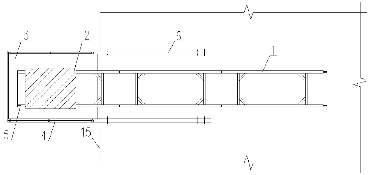
[0036] Reference Figure 1-14 , A track-type building floor material transportation device, including a guide rail and a transport trolley 2 erected on the guide rail, and also includes two sets of steel rods 6, wherein the steel rod 6 is an I-beam, and one end of the steel rod 6 is fixed by a nail In the floor, the other end of the steel rod 6 extends out of the floor line 15, that is, the other end of the steel rod 6 is suspended; there is a discharge platform 3 between the two sets of steel rods 6, and the discharge platform 3 is mainly set on the side where the steel rod 6 is suspended , One end of the guide rail extends to the unloading platform 3;
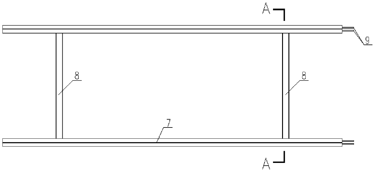
[0037] The above-mentioned guide rail is spliced by multiple sets of butting guide rails 1. The butting guide rail 1 includes two sets of I-beams 7 arranged in parallel, an angle steel 8 and a square steel plate 9 welded between the two sets of I-beams 7, and one end of the I-beam 7 Two sets of square steel plates 9 are fixed. The two groups of square steel plates 9 are respectively located on both sides of the longitudinal column of the I-beam 7. The square steel plates 9 are provided with through holes, and the column at the other end of the I-beam 7 is provided with a circular hole 71. When the two sections of butt rails 1 are spliced end to end, the two sets of square steel plates 9 at the end of the I-beam 7 are just inserted into the longitudinal columns of the other I-beam 7. The through hole on the steel plate 9 coincides with the round hole 71; the through hole on the square steel plate 9 and the round hole 71 are inserted with a fixing bolt 20, and the end of the fixing bolt 20 is inserted with a connecting pin 10 to prevent the fixing bolt 20 Out of the hole; the middle of the connecting pin 10 is provided with a strip-shaped opening. When the plug is inserted, the upper and lower ends of the connecting pin 10 are compressed and deformed inwardly. The arrangement of the middle opening facilitates the inward compression and deformation of the connecting pin 10.
[0038] The end of the docking rail 1 on the unloading platform 3 is provided with a limiting block 5; the limiting block 5 is a square bump, which is used to prevent the transport trolley 2 from derailing from the end of the docking rail 1 and limit the transport trolley 2.
[0039] The transport trolley 2 includes a bottom frame 21, a steel plate skin 11 arranged on the surface of the bottom frame 21, a driving wheel 12, a transmission rod 13, a motor 14 and a guide rail cleaning mechanism. The four sets of driving wheels 12 are respectively arranged on the bottom of the bottom frame 21, and A transmission rod 13 is connected between the side driving wheels 12, and the motor 14 is fixedly installed at the bottom of the bottom frame 21. The motor 14 drives the transmission rod 13 to rotate through a chain transmission mode. The output shaft of the motor 14 and the transmission rod 13 are both fixed Sprocket, a chain is wound between the two sets of sprockets, the motor 14 rotates through the sprocket chain to drive the transmission rod 13 to rotate, and the rotation of the transmission rod 13 drives the driving wheels 12 on both sides to rotate, so that the transport trolley 2 travels on the guide rail; The guide rail cleaning mechanism is arranged one by one on the outside of the four sets of driving wheels 12;
[0040] The above-mentioned motor 14 may be electrically connected to an external control system in a wired or wireless manner, so as to control the operation of the transportation trolley 2.
[0041] The guide rail cleaning mechanism includes a worm 16 rotatably connected to the driving wheel 12, a worm wheel 17 meshing with the worm 16, and a cleaning roller 18. The transmission rod 13 drives the worm 16 to rotate through a chain drive, that is, the transmission rod 13 and the worm 16 The ends are connected with sprockets, and a chain is arranged between the two sets of sprockets. The transmission rod 13 rotates through the sprocket chain to drive the worm 16 to rotate; the worm wheel 17 and the cleaning roller 18 are both rotatably connected to the bottom of the bottom frame 21, the worm wheel 17 The cleaning roller 18 is driven to rotate through a chain drive, that is, the upper end of the cleaning roller 18 shaft and the bottom of the worm wheel 17 are fixedly installed with sprocket wheels. There is a chain between the two sets of sprocket wheels. When the worm wheel 17 rotates, the sprocket chain can Drive the cleaning roller 18 to rotate; the bottom of the cleaning roller 18 is in contact with the surface of the I-beam 7; when the motor 14 drives the transmission rod 13 to rotate to make the transport trolley 2 run, the transmission rod 13 drives the worm 16 to rotate through the sprocket chain. The rotation of 16 will drive the worm wheel 17 to rotate. The rotation of the worm wheel 17 drives the cleaning roller 18 to rotate through the sprocket chain to clean up debris on the track surface, reducing the derailment of the transport trolley 2; the rotation of the cleaning roller 18 when the transport trolley 2 is running Direction as Figure 13 As shown, the traveling direction of the trolley is the direction of the arrow in the figure; the rotation direction of the cleaning roller 18 can be realized by adjusting the twisting direction of the worm wheel 17 and the worm 16 as a more common conventional technical means.
[0042] Further, the fixing bolt 20 is composed of a plug bolt 201 and a plug fitting 202, wherein the plug fitting 202 is a C-shaped fixing ring, the plug fitting 202 is fixed to the end of the plug bolt 201, and the connecting plug 10 is inserted into the plug In the fitting 202; only the connecting pin 10 needs to be inserted into the pin fitting 202 and hammered in during use. This arrangement facilitates the assembly and disassembly of the fixing bolt 20.
[0043] Further, a protective railing 4 is fixed on the top of the steel pole 6 extending beyond the floor edge 15 to prevent users from falling.
[0044] Further, the cleaning roller 18 is composed of a rotating shaft 181 and a cleaning plate 182 evenly arranged on the outer wall of the rotating shaft 181 along the circumference. The bottom of the cleaning plate 182 is evenly provided with bristles, and the bristles are in contact with the surface of the I-beam 7, and the bristles are selected as antistatic Brush bristles to prevent electrostatic adsorption of dust and debris; the length of the bristles is preferably 3-4mm, that is, the distance from the bottom of the cleaning plate 182 to the guide rail is 3-4mm. When there are some large debris on the track, the bristles are relatively large. It is soft, so it cannot push the heavier debris. When the height of the heavier debris is less than 4mm, the transport trolley 2 will not derail even if it passes by. When the height of the heavier debris is higher than 4mm, it is rigid The cleaning plate 182 can push debris away from the surface of the rail.
[0045] Further, the rotation shaft 181 is misaligned with the I-beam 7, and the shortest distance from the edge of the I-beam 7 away from the rotation shaft 181 to the axis of the rotation shaft 181 is smaller than the width of the cleaning plate 182; this arrangement makes the cleaning plate 182 rotate around the rotation shaft 181 The surface of I-beam 7 can be fully cleaned.
[0046] Further, four sets of baffles 19 are fixed on the side wall of the bottom frame 21, and the baffles 19 respectively correspond to the positions of the cleaning rollers 18 to prevent the roller 18 from being injured on the spot.
[0047] working principle:
[0048] When in use, put the materials on the transport trolley 2, start the motor 14 to make the transport trolley 2 travel on the guide rails to transport the materials, and after the materials are transported to the unloading platform 3, the materials can be lifted by the tower crane; The operation of the motor 14 will drive the guide rail cleaning mechanism to clean up the debris on the surface of the guide rail, reducing the risk of derailment during the transportation of the transport trolley 2;
[0049] Moreover, the rails in the rail-type building floor material transport device are convenient to splice. When splicing, the two sets of square steel plates 9 at the end of the I-beam 7 must be inserted into the longitudinal columns of the other I-beam 7. At this time, the square steel plates 9 The through hole on the upper part coincides with the round hole 71, and then the fixing bolt 20 is inserted into the through hole and the round hole 71 on the square steel plate 9, and then the connecting pin 10 is inserted into the pin fitting 202 and knocked in with a hammer. This arrangement facilitates the assembly and disassembly of the fixing bolt 20.
[0050] The above descriptions are only the preferred embodiments of the present invention and are not used to limit the present invention. For those skilled in the art, the present invention can have various modifications and changes. Any modification, equivalent replacement, improvement, etc., made within the spirit and principle of the present invention shall be included in the protection scope of the present invention.