Projection moving door device

A sliding door and projection technology, which is applied in the field of door furniture, can solve the problems of high replacement cost, inaccessibility of light, high cost of projected sliding doors, etc., and achieve the effect of cost reduction

Inactive Publication Date: 2018-09-28
未石互动科技股份有限公司
View PDF5 Cites 5 Cited by
  • Summary
  • Abstract
  • Description
  • Claims
  • Application Information

AI Technical Summary

Problems solved by technology

[0002] At present, there are many projection sliding doors on the market. Most of the projection screens of projection sliding doors use dimming glass and dimming glass controller to control the transparent and opaque state of the glass to switch. Due to various conditions, currently on the market The mass-produced dimmable glass is almost all electronically controlled dimmable glass. The principle of electronically controlled dimmable glass is: when the electronically controlled product is turned off, the liquid crystal molecules in the electronically controlled dimmable glass will show irregular distribution. state, so that light cannot enter, so that the electronically controlled glass presents an opaque appearance; although the price of dimming glass has dropped from tens of thousands of dollars per square meter when it first came out to less than 10,000 yuan per square meter at present, due to the high cost For other reasons, the price of dimming glass has been relatively high, which also leads to the high cost of general projection sliding doors, and it is difficult to be widely used and popularized.
[0003] Moreover, the sliding door made of dimming glass, once the dimming glass is damaged, will cause the entire sliding door to lose the projection body, and then cannot continue to realize the projection function, and the replacement is inconvenient and the replacement cost is high. Therefore, to solve these problems, we need A projection sliding door that can be popularized at low cost and can realize the projection function

Method used


Image

  • Projection moving door device
  • Projection moving door device
  • Projection moving door device

Examples


Embodiment Construction

[0023] The following will clearly and completely describe the technical solutions in the embodiments of the present invention with reference to the accompanying drawings in the embodiments of the present invention. Obviously, the described embodiments are only some, not all, embodiments of the present invention. Based on the embodiments of the present invention, all other embodiments obtained by persons of ordinary skill in the art without making creative efforts belong to the protection scope of the present invention.

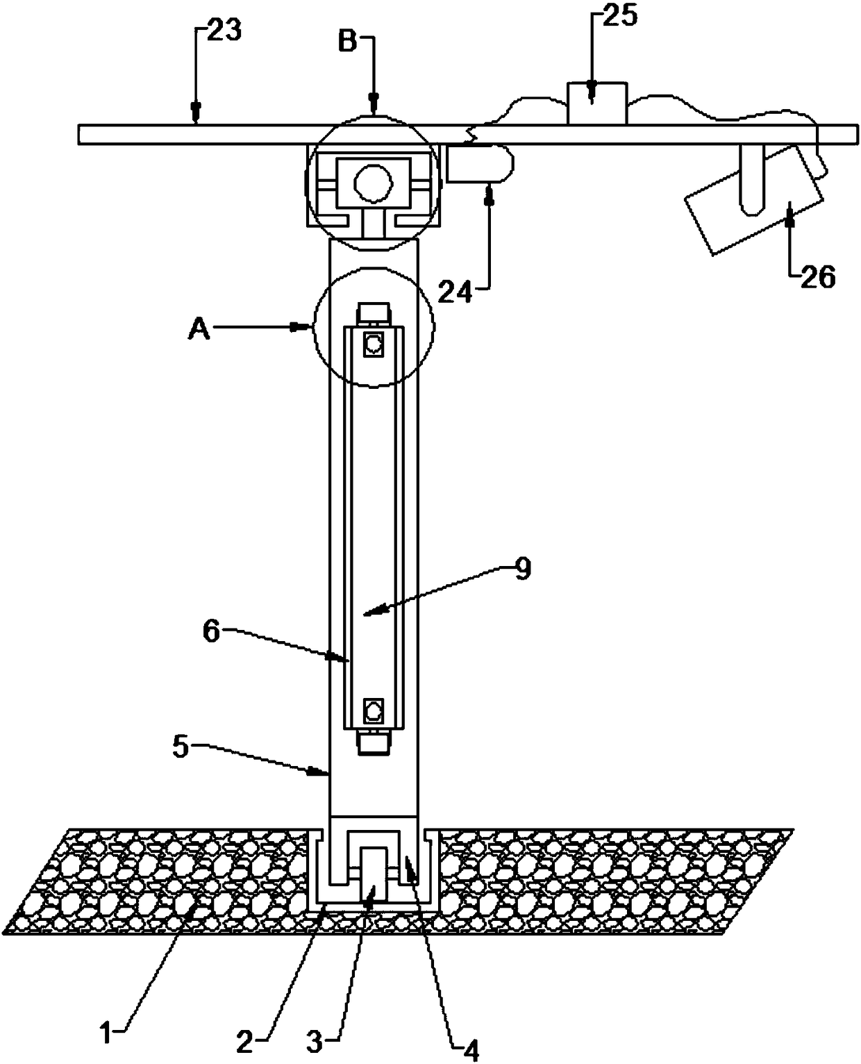
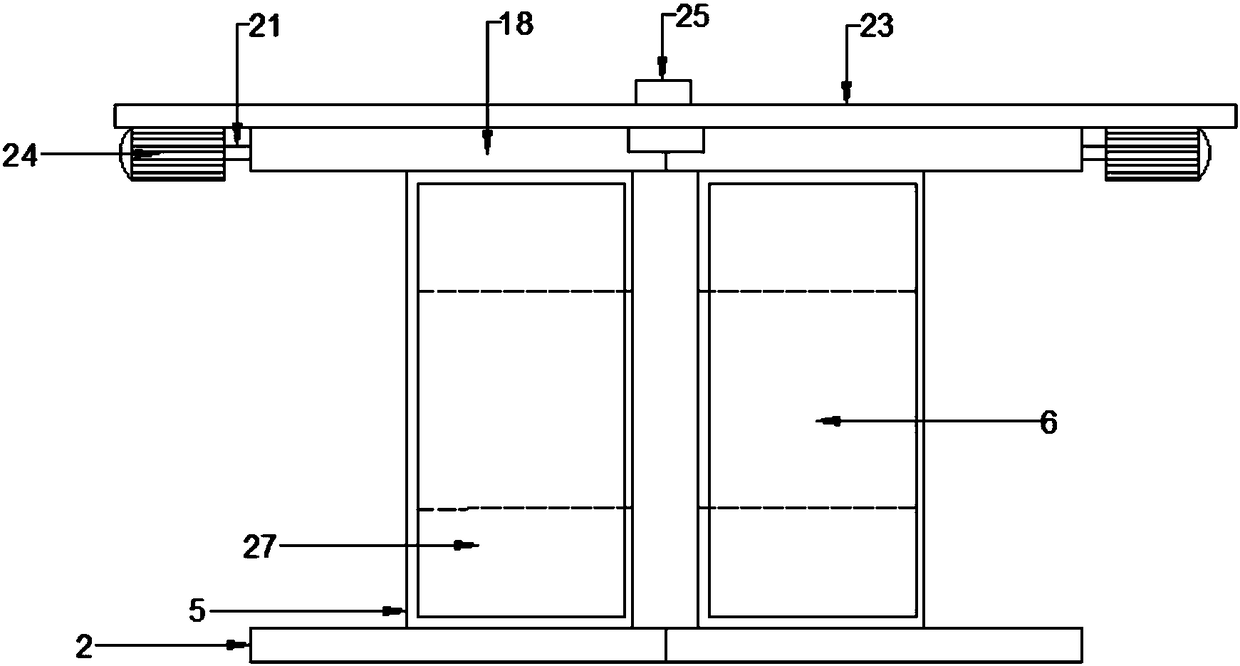
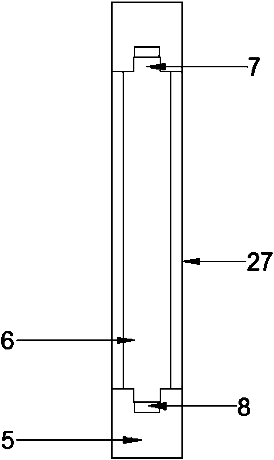
[0024] see Figure 1-7 , in an embodiment of the present invention, a projection sliding door device, including installation ground 1, guide rail groove 2, guide wheel 3, guide wheel frame 4, glass frame 5, curtain groove 6, bump slide groove 7, bump card slot 8. Curtain panel 9, curtain panel groove 10, support spring 11, adjustment hole 12, connecting plate 13, pressure rod 14, bump connecting rod 15, fixed bump 16, boom 17, suspension channel steel 18, limi...


PUM


Abstract

The invention discloses a projection moving door device. Guiding wheels are rotatably fixed to the bottoms of glass frames through guiding wheel frames, the guiding wheels are supported on the groovebottoms of guide-track grooves, and sliding blocks are fixed to the tops of the glass frames through hanger rods. Screw rods are sleeved on the sliding blocks in a threaded mode, the screw rods are rotatably fixed in suspension channel steels, limiting rods are fixed to the two side walls of the sliding blocks, and the outer side ends of the limiting rods are clamped in limiting openings. Drivingmotors are fixedly arranged on the base faces of three-ply boards on the both sides of the glass frames, infrared sensors and a projector are arranged in front of the suspension channel steels, two moving door glasses are fixed on the inner side faces and the outer side faces of the glass frames in an agglutinating mode, and a curtain groove is formed in an empty cavity between the moving door glasses, a curtain plate is arranged in the curtain groove, curtain plate grooves are formed in the bottom face of the curtain plate, and the curtain plate grooves are clamped in protrusion clamping grooves through fixed protrusions. The function of moving door projection is realized by the dismountable curtain plate, the manufacture cost is low, and the maintenance is convenient.

Description

technical field [0001] The invention relates to the field of door furniture, in particular to a projection sliding door device. Background technique [0002] At present, there are many projection sliding doors on the market. Most of the projection screens of projection sliding doors use dimming glass and dimming glass controller to control the transparent and opaque state of the glass to switch. Due to various conditions, currently on the market The mass-produced dimmable glass is almost all electronically controlled dimmable glass. The principle of electronically controlled dimmable glass is: when the electronically controlled product is turned off, the liquid crystal molecules in the electronically controlled dimmable glass will show irregular distribution. state, so that light cannot enter, so that the electronically controlled glass presents an opaque appearance; although the price of dimming glass has dropped from tens of thousands of dollars per square meter when it fi...

Claims


Application Information

Patent Timeline
Patent Type & Authority Applications(China)
IPC IPC(8): E06B3/02E06B3/46E06B7/28E05F15/73E05F15/632G03B21/56
CPCE06B3/02E05F15/632E05F15/73E06B3/4636E06B7/28G03B21/56
Inventor 李林
Owner 未石互动科技股份有限公司
Why Eureka
Try Eureka