Radar echo interference removing method

A technology of radar echo and de-jamming, applied in the direction of radio wave measurement systems, instruments, etc., can solve the problems of not being detected, affecting the peak value of the target spectrum, etc.

Inactive Publication Date: 2018-09-28
厦门镭通智能科技有限公司
View PDF3 Cites 4 Cited by
  • Summary
  • Abstract
  • Description
  • Claims
  • Application Information

AI Technical Summary

Problems solved by technology

Among them, the echo signal received by the radar contains a modulation leakage signal, which will af

Method used


Image

  • Radar echo interference removing method
  • Radar echo interference removing method
  • Radar echo interference removing method

Examples


Embodiment Construction

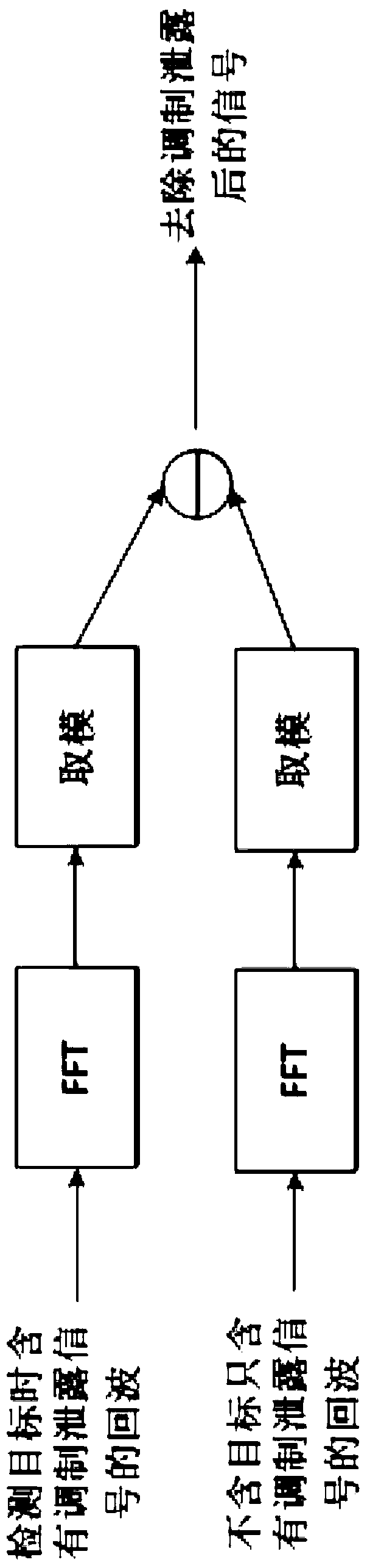
[0014] Such as figure 1 As shown, the present invention discloses a radar echo dejamming method, which includes the following steps:

[0015] Step 1. When there is no target in the detection area, the radar transmits a radar wave signal to the detection area, and receives a corresponding echo signal, which is processed by an A / D converter and stored as a modulated leakage signal f1;

[0016] Step 2, when there is a target in the detection area, send the radar wave signal to the detection area, and receive the corresponding echo signal, which is stored as echo signal f2 after being processed by the A / D converter;

[0017] Step 3, perform FFT transformation on the modulation leakage signal f1 and the echo signal f2 respectively, and then take the modulus to obtain the signal F1 and the signal F2;

[0018] Step 4, the signal F1 is subtracted from the signal F2 to obtain the target echo signal S after the modulation signal is removed.

[0019] In order to elaborate the content o...


PUM


Abstract

The invention relates to a radar echo interference removing method. Echo signal obtained when no target passes through are taken as modulation leakage signals, the pre-detected modulation leakage signals are subtracted from detected target echo signals to obtain target echo signals. Even targets with low spectrum peaks can be detected, and accordingly the target detection rate is increased.

Description

technical field [0001] The invention relates to the field of radar detection, in particular to a method for removing interference from radar echoes. Background technique [0002] The commonly used target detection principle is to use the radar echo signal to do FFT (Fast Fourier Transform) to find the position of the spectral peak to determine the target. Among them, the echo signal received by the radar contains a modulation leakage signal, which will affect the spectral peak of the target, and some targets with lower spectral peaks will not be detected. Contents of the invention [0003] The object of the present invention is to provide a method for removing interference from radar echoes, which can remove environmental interference through a simple method, thereby improving the target detection rate. [0004] In order to achieve the above object, the technical scheme adopted in the present invention is: [0005] A radar echo dejamming method, it comprises the followin...

Claims


Application Information

Patent Timeline
IPC IPC(8): G01S7/41G01S7/36
CPCG01S7/36G01S7/41
Inventor 张贻雄邓振淼秦牧云
Owner 厦门镭通智能科技有限公司
Why Eureka
Try Eureka