A Reactive Parallel Compensation Method

A compensation method and parallel technology, applied in the direction of reactive power compensation, reactive power adjustment/elimination/compensation, AC network circuit, etc., to achieve high compensation accuracy, improve effect, and reduce compensation pressure.

Active Publication Date: 2021-09-28
YUNNAN POWER GRID CO LTD ELECTRIC POWER RES INST +1
View PDF3 Cites 0 Cited by
  • Summary
  • Abstract
  • Description
  • Claims
  • Application Information

AI Technical Summary

Problems solved by technology

[0005] This application provides a reactive power parallel compensation method to solve the reactive power parallel compensation problem of the power grid with DG

Method used


Image

  • A Reactive Parallel Compensation Method
  • A Reactive Parallel Compensation Method
  • A Reactive Parallel Compensation Method

Examples


Embodiment Construction

[0029] In order to enable those skilled in the art to better understand the technical solutions in the present application, the technical solutions in the embodiments of the present application will be clearly and completely described below in conjunction with the drawings in the embodiments of the present application. Obviously, the described The embodiments are only some of the embodiments of the present application, not all of them. Based on the embodiments in this application, all other embodiments obtained by persons of ordinary skill in the art without creative efforts shall fall within the scope of protection of this application.

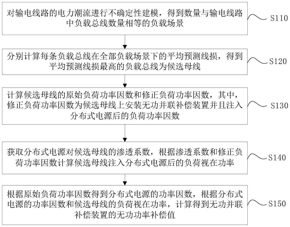
[0030] see figure 1 , is a schematic flowchart of a reactive power parallel compensation method provided in the embodiment of the present application, as shown in figure 1 As shown, the reactive power parallel compensation method provided in the embodiment of the present application specifically includes the following steps:

[0031] Step S...


PUM


Abstract

The application provides a reactive power parallel compensation method, which includes: modeling the power flow uncertainty of the transmission line to obtain load scenarios whose number is equal to the number of load buses in the transmission line; According to the average predicted line loss in the scene, the load bus with the highest average predicted line loss is obtained as the candidate bus; the original load power factor and the corrected load power factor of the candidate bus are calculated; the penetration coefficient of the distributed power supply to the candidate bus is obtained, according to the penetration coefficient and Correct the load power factor to calculate the apparent power of the load after the candidate bus is injected into the distributed power; get the power factor of the distributed power according to the original load power factor, and calculate the no The reactive power compensation value of the parallel compensation device. The reactive power parallel compensation method provided by this application is based on uncertain line loss prediction, and the compensation effect is good.

Description

technical field [0001] The present application relates to the technical field of power system power flow, and in particular to a reactive parallel compensation method. Background technique [0002] In a series of processes of power transmission from power plants to customers, reducing power loss and improving power reliability are important work goals. With the emergence of smart grid technology, distributed power generation has developed rapidly. Distributed power generation utilizes DG (Distributed generator, distributed power) arranged on the distribution network or distributed near the load to cooperate with the existing power grid, which greatly improves the reliability of power supply. [0003] As for power loss, in the prior art, parallel reactive power compensation equipment is usually installed in the power grid to solve it. Parallel reactive power compensation equipment is used to provide reactive power consumed by inductive loads in the grid, thereby reducing th...

Claims


Application Information

Patent Timeline
Patent Type & Authority Patents(China)
IPC IPC(8): H02J3/18
CPCH02J3/1821H02J2203/20Y02E40/30
Inventor 王恩曹敏李坤刘清蝉杨成涛沈鑫张万杰邵方冰李博李亚丽李波李燕唐标翟少磊马金才
Owner YUNNAN POWER GRID CO LTD ELECTRIC POWER RES INST
Why Eureka
Try Eureka