Three-level inverter circuit

A three-level inverter and circuit technology, applied in the direction of circuit devices, AC network circuits, electrical components, etc., can solve the problems of switching capacitor voltage rise, unfavorable output power quality, multi-element devices, etc., to achieve leakage current elimination and voltage stability , Improving the effect of reactive power compensation ability

Pending Publication Date: 2022-05-27
HUANENG GUANYUN CLEAN ENERGY CO LTD +2
View PDF0 Cites 0 Cited by
  • Summary
  • Abstract
  • Description
  • Claims
  • Application Information

AI Technical Summary

Problems solved by technology

In order to realize the connection between the neutral line of the grid and the photovoltaic panel, the common-ground inverter circuit needs to use more components, and i

Method used


Image

  • Three-level inverter circuit
  • Three-level inverter circuit
  • Three-level inverter circuit

Examples


Example Embodiment

[0020] The present invention will be described in detail below with reference to the accompanying drawings and embodiments of the present invention.

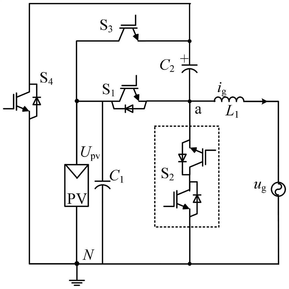
[0021] see attached figure 1 , a three-level inverter circuit of the present invention includes: a photovoltaic DC power supply U pv , the first capacitor C 1 , the second capacitor C 2 , the first power switch tube S 1 , back-to-back second power switch tube S 2 , bidirectional third power switch tube S 3 , the fourth power switch tube S 4 , AC filter inductor L 1 and single-phase AC distribution network u g .

[0022] The three-level inverter circuit, photovoltaic DC power supply U pv The positive pole of the first capacitor C 1 The positive pole, the first power switch tube S 1 The drain and bidirectional third power switch tube S 3 The collector is connected; the first power switch tube S 1 The source and back-to-back second power switch tube S 2 One end of the source, the second capacitor C 2 The negative pol...


PUM


Abstract

The invention discloses a three-level inverter circuit which comprises a power switch, a capacitor and an alternating current filter inductor. The inverter circuit outputs a three-level voltage, and the harmonic content is reduced compared with a two-level structure; according to the inverter circuit, current flows through only one switching tube under the energy transfer modes of the positive half cycle and the negative half cycle of a power grid, so that the switching loss is reduced; a charging loop of the switched capacitor by an input direct current source is separated from a follow current loop of a power grid, and the current of the power grid does not pass through the switched capacitor in a follow current mode of 0 level, so that the voltage of the switched capacitor of the circuit is not greatly increased under a non-unity power factor; the neutral point of the power grid of the inverter circuit is directly connected with the negative electrode of the photovoltaic cell panel to form a common-ground structure, so that the generation of leakage current is effectively inhibited, and therefore, the inverter circuit, as a non-isolated inverter, has a relatively good application value in a medium-and-small-power non-isolated photovoltaic grid-connected inverter system.

Description

technical field [0001] The invention relates to a three-level inverter circuit technology, and belongs to the technical field of inverter circuit topology. Background technique [0002] Driven by the global new energy revolution, countries around the world have set clear goals for new energy power generation. The EU Ministry of Energy proposes that by 2050, the EU plans to generate 80% of the total power generation from new energy sources. As an important member of new energy, photovoltaic has broad development prospects. Due to the inclusion of power frequency or high frequency transformers in the traditional isolated photovoltaic grid-connected inverter structure, the overall photovoltaic efficiency and power density are reduced, which is not conducive to the large-scale popularization of photovoltaic power generation systems in the future. [0003] There is no transformer in the non-isolated photovoltaic grid-connected inverter circuit, so it has great advantages over t...

Claims


Application Information

Patent Timeline
IPC IPC(8): H02J3/38H02M7/5387H02M7/5395H02M1/42H02M1/12
CPCH02J3/381H02M7/53871H02M7/5395H02M1/42H02M1/126H02J2300/24Y02E10/56
Inventor 曹庆伟牛晨晖陈晓路杭兆峰郑枫姚中原杨立华管春雨刘溟江肖华锋陈庆东
Owner HUANENG GUANYUN CLEAN ENERGY CO LTD
Why Eureka
Try Eureka