
Deriving tooth condition information for populating digital dental charts

A tooth condition, tooth technology, applied in the direction of radiological diagnostic equipment, dentistry, informatics, etc., can solve problems prone to human error, time-consuming, etc.

Active Publication Date: 2018-09-28
3SHAPE AS
View PDF7 Cites 2 Cited by
  • Summary
  • Abstract
  • Description
  • Claims
  • Application Information

AI Technical Summary

Problems solved by technology

This is time consuming and prone to human error, e.g. annotating information to the wrong part of the tooth or even the wrong tooth

Method used


Image

  • Deriving tooth condition information for populating digital dental charts
  • Deriving tooth condition information for populating digital dental charts
  • Deriving tooth condition information for populating digital dental charts

Examples


Embodiment Construction

[0241] In the following description, reference is made to the accompanying drawings, which show by way of example how the invention may be practiced.

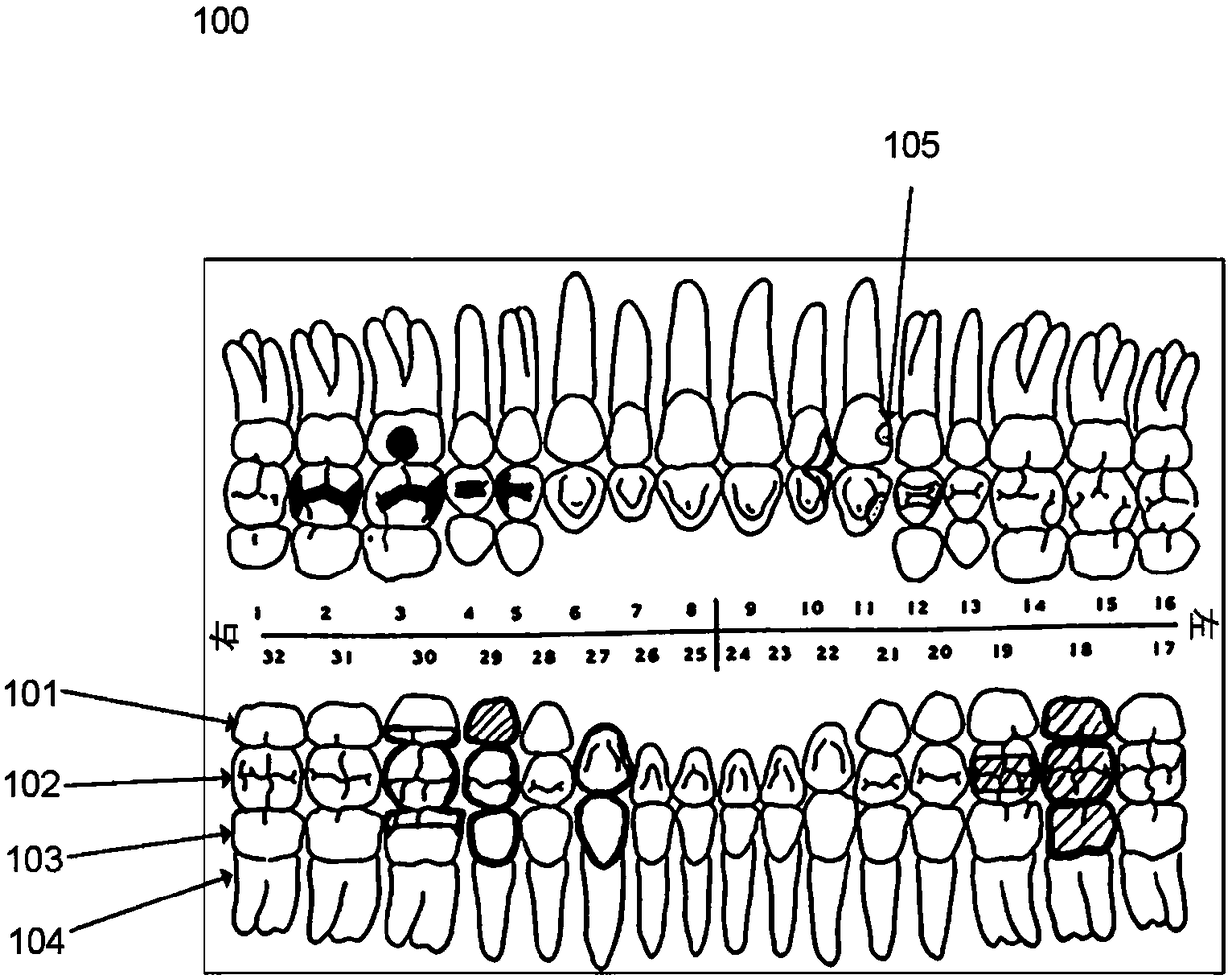
[0242] figure 1 A dental chart for recording tooth condition information is shown.

[0243] The dental chart 100 has standardized areas representing the surface and root of each tooth. For example, the dental chart 100 has regions 101, 102 and 103 representing the lingual, occlusal and buccal surfaces of tooth #32, respectively, while region 104 represents the root of the tooth.

[0244] Indicates the area on the surface of a tooth that can be shaped to resemble a tooth, or even exceed figure 1 Seen or more schematically. Most dental charts have areas for all the teeth normally found inside a person's mouth, as in the figure 1 shown in the diagram in the illustration.

[0245] Different symbols can be used to visualize the dental condition information derived for the patient's teeth. exist figure 1 In the dental diagram ...


PUM


Abstract

Disclosed are methods and digital tools for deriving tooth condition information for a patient's teeth, for populating a digital dental chart with derived tooth condition information, and for generating an electronic data record containing such information.

Description

technical field [0001] The present invention generally relates to methods, systems, computer program products and digital environments for deriving dental condition information of a patient's teeth and for populating a dental chart with dental condition information. More specifically, the present invention relates to methods, systems, computer program products and digital environments for identifying individual teeth from a digital three-dimensional representation of a patient's teeth, and the derived tooth condition information is associated with the individual teeth. Background technique [0002] Dental practice management systems often use dental charts to store information about a patient's dental condition. This dental diagram is considered an effective tool for visualizing information about the condition of a patient's teeth. [0003] Standardized dental charts typically have areas representing the surfaces of individual teeth normally found in a patient's mouth. In ...

Claims


Application Information

Patent Timeline
Patent Type & Authority Applications(China)
IPC IPC(8): A61C9/00A61B6/14A61B5/00G16H30/20
CPCA61C9/0046A61B5/0088G16H10/60G16H50/20A61B5/7475A61B5/0062A61B5/0066A61B5/0071A61C13/0004A61B5/4547G16H30/20A61B6/512G06T3/14G06T7/12G06T7/32G06T7/70G16H30/40A61B5/1032G06T7/0014G06T2207/10028G06T2207/30036
Inventor 迈克·范德普尔R·费斯克卡尔-约瑟夫·霍伦贝克
Owner 3SHAPE AS
Learn More