Rotary vane steering gear and mounting method thereof

An installation method and steering gear technology, which are applied to the fluid pressure actuating device and other directions, can solve the problems of affecting the normal operation of the rotary vane steering gear, difficult installation of the rotary vane steering gear, and damage to the end face sealing ring.

Inactive Publication Date: 2018-10-02
WUHAN UNIV OF SCI & TECH
View PDF1 Cites 0 Cited by
  • Summary
  • Abstract
  • Description
  • Claims
  • Application Information

AI Technical Summary

Problems solved by technology

[0003] The purpose of the present invention is to solve the difficulty of installing the existing rotary blade steering gear. The blade and the end face seal ring are easily damaged during the installation process, and sometimes it is impossible to predict whether the end face seal ri

Method used


Image

  • Rotary vane steering gear and mounting method thereof
  • Rotary vane steering gear and mounting method thereof
  • Rotary vane steering gear and mounting method thereof

Examples


Embodiment Construction

[0021] In order to make the object, technical solution and advantages of the present invention clearer, the implementation manner of the present invention will be further described in detail below in conjunction with the accompanying drawings.

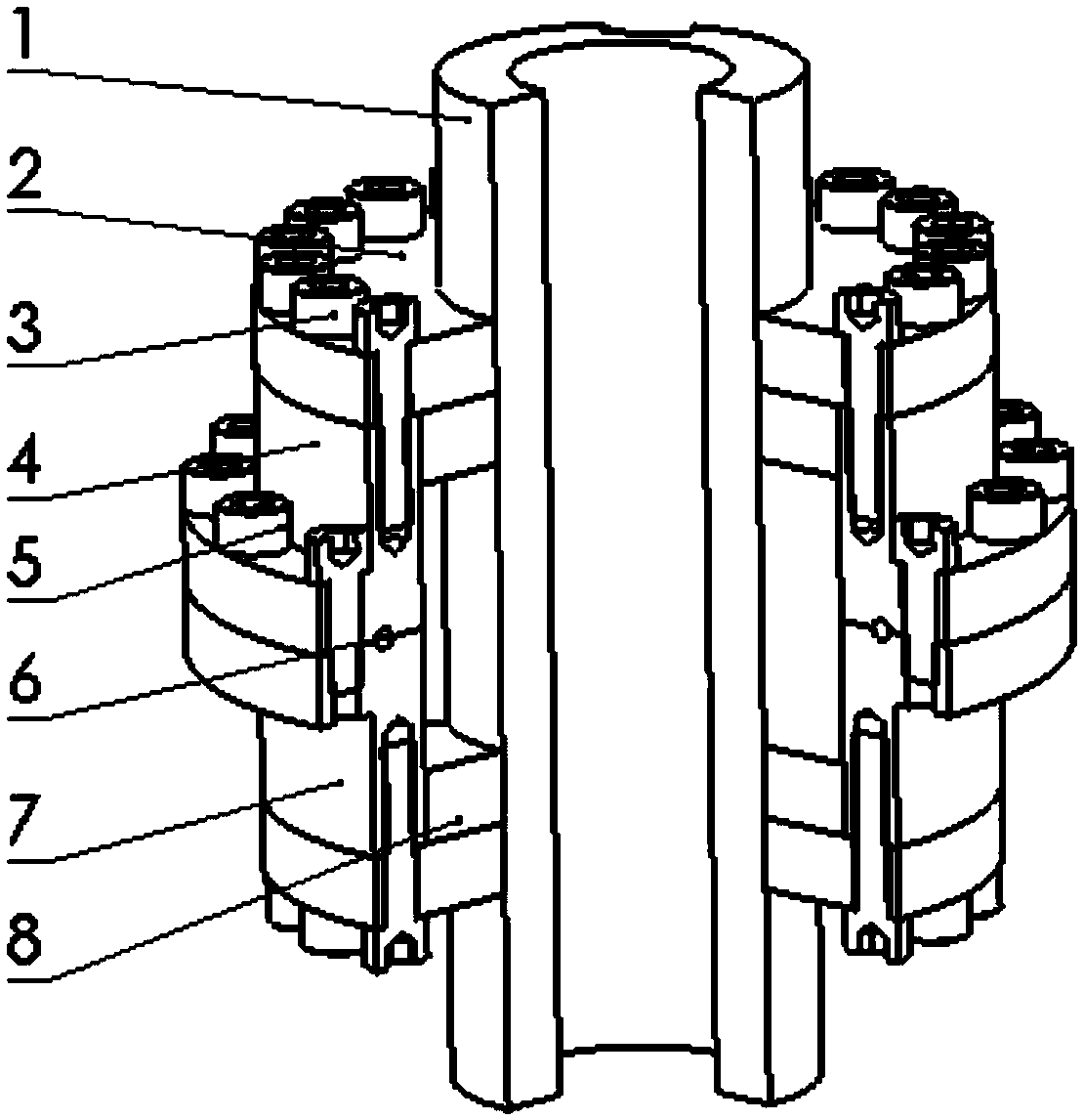
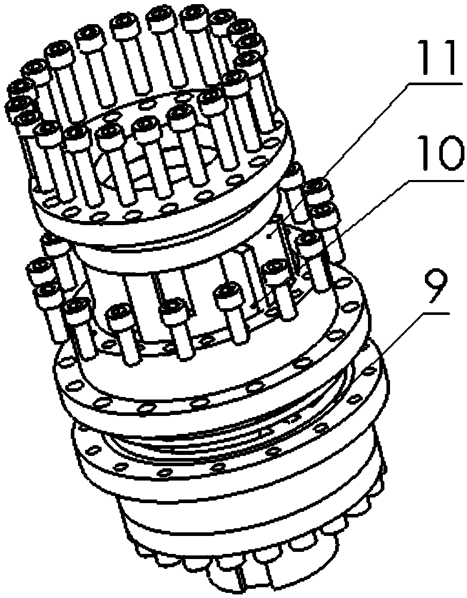
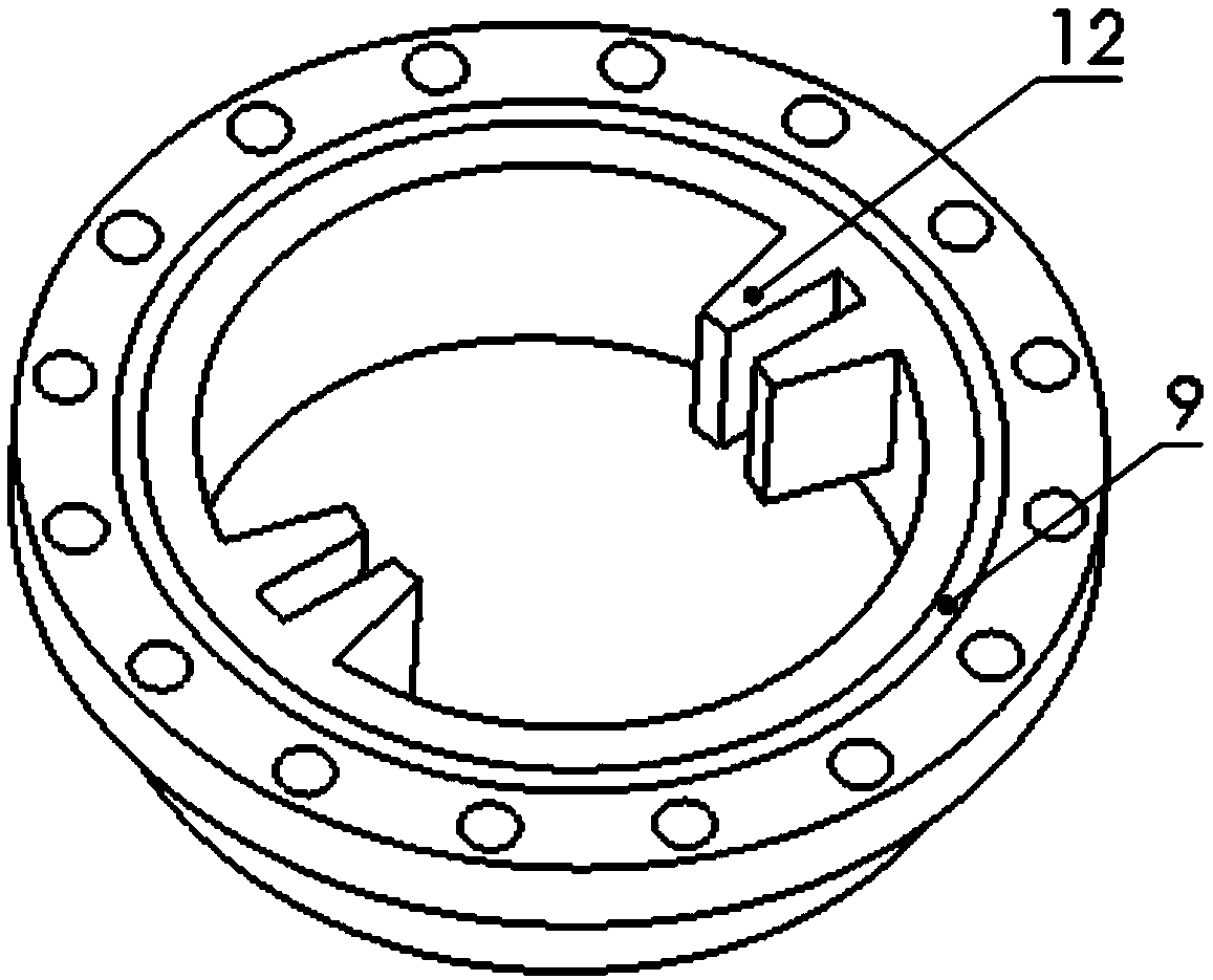
[0022] like Figures 1 to 5 As shown, a rotary vane steering gear includes a rotor 1, a cover plate 2, a cover plate screw 3, an upper cylinder body 4, cylinder body screws 5, an O-ring 6, a lower cylinder body 7, an end face sealing ring 8, an O-ring Ring groove 9, rotor blade 10, cylinder blade 11, lower cylinder blade support 12, rotor blade support 13, keyway 14 and upper cylinder blade support (not shown).

[0023] The upper cylinder 4 and the lower cylinder 7 have the same symmetrical structure, and the upper cylinder blade support and the lower cylinder blade support 12 are respectively arranged inside the two, and the upper cylinder 4 Combining up and down with the lower side cylinder 7 together constitutes the cylinder part o...


PUM


Abstract

A rotary vane steering gear comprises a rotor, a cylinder block, rotor vane supports, rotor vanes, cylinder block vane supports, cylinder block vanes and two cover plates, and is characterized in thatthe cylinder block is formed by combining an upper side cylinder block and a lower side cylinder block; the upper side cylinder block and the lower side cylinder block are of a symmetrical structure;the inner wall of the upper side cylinder block and the inner wall of the lower side cylinder block are provided with upper side cylinder block vane supports and lower side cylinder block vane supports correspondingly; after the upper side cylinder block and the lower side cylinder block are combined up and down, the upper side cylinder block vane supports and the lower side cylinder block vane supports are combined into the whole cylinder block vane supports; the rotor vane supports are arranged in the middle of the rotor, and the rotor vane supports and the rotor are of an integrally formedstructure; the rotor is mounted in the cylinder block; the rotor vanes are mounted in the rotor vane supports; the cylinder block vanes are mounted in the cylinder block vane supports; the two coverplates are in an annular shape and are packaged on the two sides of the cylinder block correspondingly; and the two ends of the rotor extend out of the cover plates.

Description

technical field [0001] The invention belongs to the technical field of hydraulic equipment sealing, in particular to a rotary vane steering gear and an installation method thereof. Background technique [0002] Rotary vane steering gear or vane hydraulic swing cylinder is a hydraulic drive device that converts hydraulic energy into mechanical energy and converts linear motion into reciprocating rotary motion. The vane hydraulic swing cylinder has compact structure, large torque, and good stability. Advantages, the vane hydraulic swing cylinder connects the driven equipment and the cylinder rotor through a key, the oil acts on the rotor vane, and converts the oil pressure that pushes the vane to the rotor, and then drives the driven equipment connected by the shaft through the rotor drive equipment. Now it is mainly used in aerospace, ships, automobiles, etc., and the prospect is very broad. The existing hydraulic oscillating cylinders mainly have the following problems: 1....

Claims


Application Information

Patent Timeline
IPC IPC(8): F15B15/12
CPCF15B15/12
Inventor 罗刚谢良喜吴攀峰李卫飞罗中正高强
Owner WUHAN UNIV OF SCI & TECH
Why Eureka
Try Eureka