Entity configuration method, device and system, CU-U

A configuration method, CU-U technology, applied in network traffic/resource management, electrical components, connection management, etc., can solve problems such as unproposed solutions

Active Publication Date: 2018-10-02
ZTE CORP
View PDF6 Cites 4 Cited by
  • Summary
  • Abstract
  • Description
  • Claims
  • Application Information

AI Technical Summary

Problems solved by technology

[0006] For the above-mentioned technical problems in related technologies, no effective solution has been proposed yet

Method used


Image

  • Entity configuration method, device and system, CU-U
  • Entity configuration method, device and system, CU-U
  • Entity configuration method, device and system, CU-U

Examples


Embodiment 1

[0078] In this embodiment, an entity configuration method is provided, which can run on the above-mentioned image 3 In the described architecture, Figure 4 is a flowchart of an entity configuration method according to an embodiment of the present invention, such as Figure 4 As shown, the process includes the following steps:

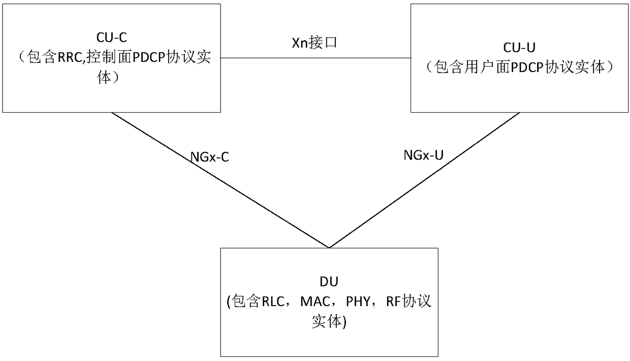
[0079] Step S402, obtain specified information for configuring each packet data convergence protocol PDCP entity that processes the data radio bearer through the Xn interface, where the Xn interface is between the control plane PDCP entity CU-C and the user plane PDCP entity CU-U the interface between;

[0080] Step S404, perform a configuration operation on each PDCP entity according to the specified information.

[0081] Through the above steps, since the specified information for configuring each PDCP entity that processes data radio bearers can be obtained through the Xn interface, and then each of the above PDCP entities can be configured acco...

Embodiment 2

[0109] This embodiment also provides an entity configuration device, which is used to implement the above embodiments and preferred implementation manners, and what has been described will not be repeated. As used below, the term "module" may be a combination of software and / or hardware that realizes a predetermined function. Although the devices described in the following embodiments are preferably implemented in software, implementations in hardware, or a combination of software and hardware are also possible and contemplated.

[0110] Figure 5 is a structural block diagram of an entity configuration device according to an embodiment of the present invention, such as Figure 5 As shown, the device includes:

[0111] The obtaining module 52 is configured to obtain specified information for configuring each packet data convergence protocol PDCP entity that processes the data radio bearer through the Xn interface, where the Xn interface is the control plane PDCP entity CU-C ...

Embodiment 3

[0141] The embodiment of the present invention also provides a user plane packet data convergence protocol PDCP entity CU-U, Figure 6 is a structural block diagram of the CU-U provided according to an embodiment of the present invention, such as Figure 6 As shown, the CU-U includes:

[0142] The radio frequency module 62 is configured to obtain specified information for configuring each packet data convergence protocol PDCP entity that processes the data radio bearer through the Xn interface, where the Xn interface is the control plane PDCP entity CU-C and the user plane PDCP entity CU - the interface between U;

[0143] The processor 64 is connected to the above-mentioned radio frequency module 62, and is configured to configure each PDCP entity according to specified information.

[0144] Through the above CU-U, since the specified information for configuring each packet data convergence protocol PDCP entity that processes the data radio bearer can be obtained through the ...


PUM


Abstract

The present invention provides an entity configuration method, an entity configuration device, an entity configuration system, and a CU-U. The entity configuration method includes the following stepsthat: specified information for configuring each packet data convergence protocol (PDCP) entity for processing data radio bearers is obtained through an Xn interface, wherein the Xn interface is an interface between a control plane PDCP entity CU-C and a user plane PDCP entity CU-U; and configuration operation is performed on each PDCP entity according to the specified information. With the entityconfiguration method, the entity configuration device, the entity configuration system, and the CU-U of the invention adopted, the problem of how to implement the configuration of a CU-U protocol entity is solved, and centralized service aggregation is realized.

Description

technical field [0001] The present invention relates to the field of wireless communication, in particular to an entity configuration method, device and system, and a CU-U. Background technique [0002] In the fifth generation (5G for short) mobile communications, massive connections and higher rate requirements for users require the baseband processing unit (Building Baseband Unit, BBU for short) and remote radio frequency in long term evolution (Long Term Evolution, short for LTE). The transmission capacity of the fronthaul interface Common Public Radio Interface (CPRI) between Remote Radio Units (RRU for short) poses a great challenge, because the CPRI interface transmits after processing such as physical layer coding For IQ signals, the CPRI interface has relatively large requirements for transmission delay and bandwidth. If the 5G air interface rate increases to tens of Gbps, the traffic demand of the CPRI interface will rise to the Tbps level, which will bring huge pr...

Claims


Application Information

Patent Timeline
Patent Type & Authority Applications(China)
IPC IPC(8): H04W24/02H04W28/24H04W76/00H04W76/11
CPCH04W24/02H04W28/24H04W76/00H04W76/18H04W76/11H04W28/0268H04W80/02H04W80/08
Inventor 高音何青春黄河
Owner ZTE CORP
Why Eureka
Try Eureka