Combined mold and duct wall molding method

A combined mold and duct technology, applied in the field of molds, can solve problems affecting the overall mechanical properties of the duct wall, and achieve the effect of easy demoulding

Pending Publication Date: 2018-10-09
SHEN ZHEN KUANG CHI HEZHONG TECH LTD
View PDF0 Cites 5 Cited by
  • Summary
  • Abstract
  • Description
  • Claims
  • Application Information

AI Technical Summary

Problems solved by technology

[0003] However, for the manufacturing process of this kind of carbon fiber cylindrical parts, the existing schemes mostly use the method of connecting the parts after forming, that is, the same parts are molded and then the whole is made into a whole by mechanical connection or cementation. Although This scheme simplifies the design of the mold, but the later reconnection will affect the overall mechanical properties of the duct wall

Method used


Image

  • Combined mold and duct wall molding method
  • Combined mold and duct wall molding method
  • Combined mold and duct wall molding method

Examples


Embodiment Construction

[0029] The following will clearly and completely describe the technical solutions in the embodiments of the present invention with reference to the accompanying drawings in the embodiments of the present invention. Obviously, the described embodiments are only some, not all, embodiments of the present invention. All other embodiments obtained by persons of ordinary skill in the art based on the embodiments of the present invention belong to the protection scope of the present invention.

[0030] According to an embodiment of the present invention, a combined mold is provided.

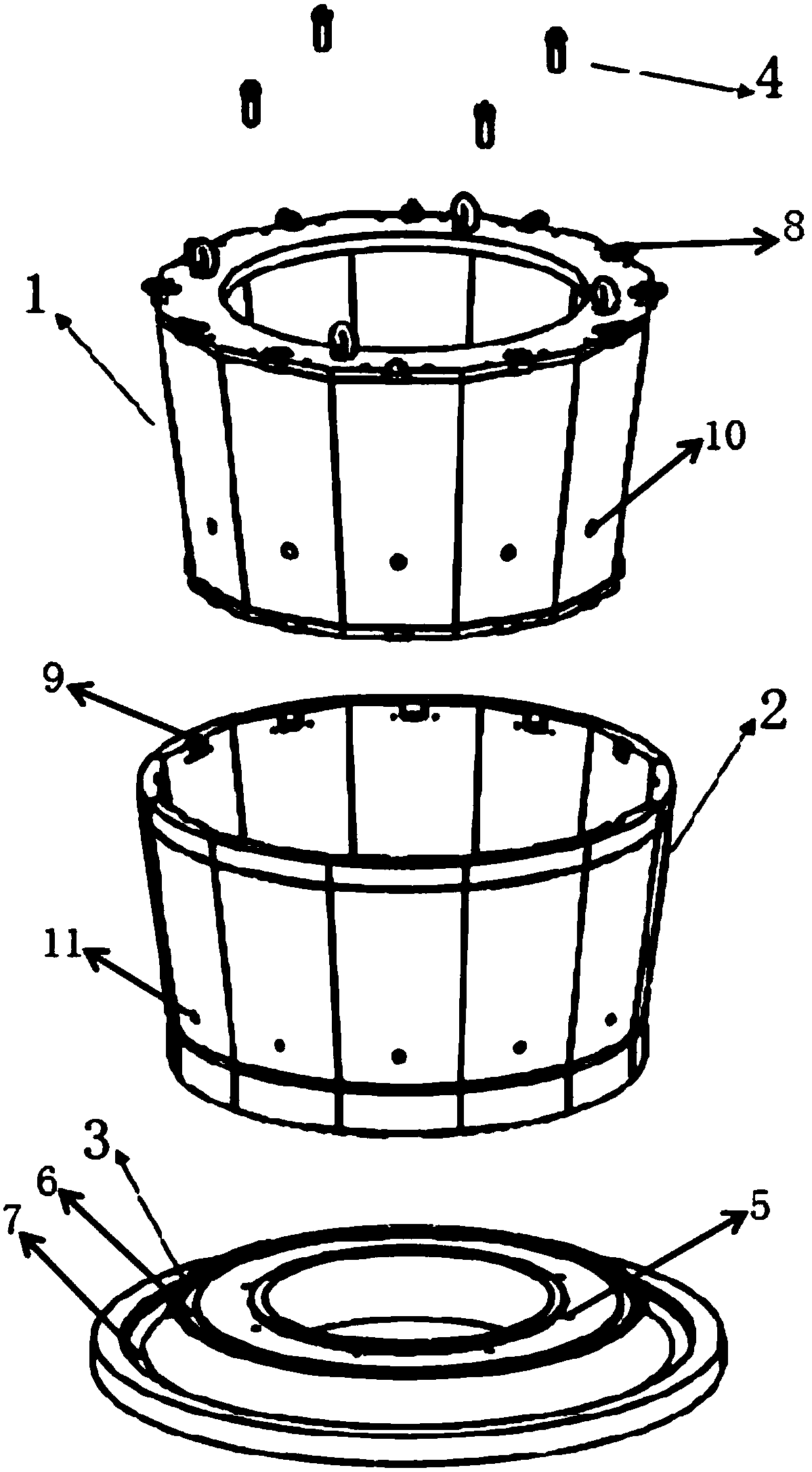
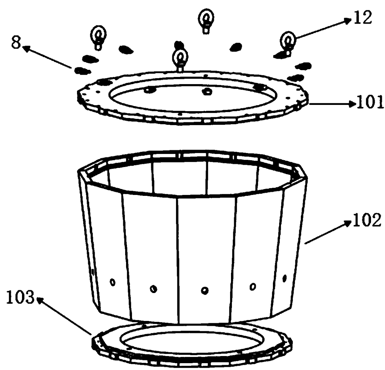
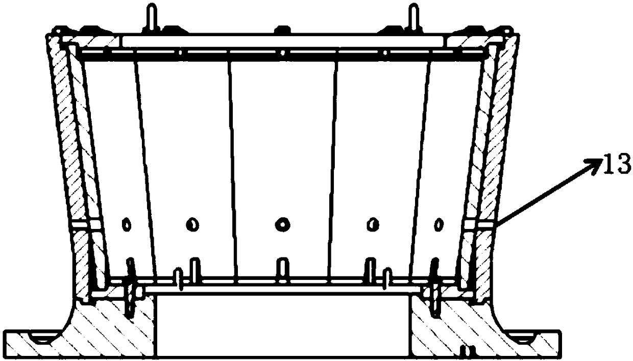
[0031] Such as figure 1 with image 3 As shown, the combined mold for forming the duct wall according to the embodiment of the present invention includes: a core mold 1, a tile mold 2, and an ear piece mold 3, wherein the core mold 1 is attached to the inner surface of the tile mold 2, The lower side of the core mold 1 is firmly connected with the ear piece mold 3 for forming the prepreg layer.

[00...


PUM


Abstract

The invention provides a combined mold and a duct wall molding method. The combined mold for molding a duct wall comprises a core mold, a tile mold and a lug sheet mold, wherein the core mold is attached to the inner side surface of the tile mold, and the lower side of the core mold is tightly and fixedly connected to the lug sheet mold so as to carry out layer stacking molding on a prepreg. According to the present invention, through the combined mold, the whole mold is divided into the core mold, the tile mold and the lug sheet mold, and the core is attached to the inner side surface of thecore so as to retain the shape and ensure the rigidity of the whole mold through the core mold, such that the integrated molding of the duct wall can be completed by combing the core mold, the tile core and the lug sheet cold; and the demolding process is easy through the form of the combined mold.

Description

technical field [0001] The invention relates to a mold, in particular to a combined mold and duct wall forming method. Background technique [0002] Ducted fan refers to a propulsion device in which a duct is arranged on the periphery of the free propeller, and the duct wall on it is mostly manufactured by carbon fiber layer laying process due to the light weight requirement. In this process, the design and manufacture of the laying mold will directly affect the difficulty of the demoulding process, which will eventually lead to the quality of the finished duct wall. Therefore, the design of the laying mold is very important. [0003] However, for the manufacturing process of this kind of carbon fiber cylindrical parts, the existing schemes mostly use the method of connecting the parts after forming, that is, the same parts are molded and then the whole is made into a whole by mechanical connection or cementation. Although This scheme simplifies the design of the mold, but ...

Claims


Application Information

Patent Timeline
Patent Type & Authority Applications(China)
IPC IPC(8): B29C70/30B29C70/54B29C33/00
CPCB29C33/00B29C70/30B29C70/54
Inventor 不公告发明人
Owner SHEN ZHEN KUANG CHI HEZHONG TECH LTD
Why Eureka
Try Eureka