Eureka AIR delivers breakthrough ideas for toughest innovation challenges, trusted by R&D personnel around the world.

Buffering and walking integrated landing device

Active Publication Date: 2017-05-31
NANJING UNIV OF AERONAUTICS & ASTRONAUTICS
View PDF7 Cites 22 Cited by
  • Summary
  • Abstract
  • Description
  • Claims
  • Application Information

AI Technical Summary

Problems solved by technology

[0006] However, there are some shortcomings in the above schemes: the above two schemes can only drive the buffer pillars to expand and retract, and the movement flexibility in posture adjustment and walking is average; the length of the buffer pillars in the former is unknown and uncertain after buffering. That is, the impact of buffering on the kinematics of the whole machine is unpredictable, and the design of separating the buffering parts from the driving parts in this scheme is not easy to transplant to other landers; only the main pillar of the latter has the buffering function , the auxiliary strut is a single function screw nut driver
This scheme can realize the attitude control of the upper platform equipped with various sensors and other payloads, but cannot move the position of the lander after buffering
[0008] In summary, the currently known landers with attitude adjustment and walking functions have deficiencies such as unstable and uncontrollable kinematics characteristics of the whole machine after buffering, low movement flexibility, and limited attitude control ability and obstacle surmounting ability when walking. To be improved

Method used


Image

  • Buffering and walking integrated landing device
  • Buffering and walking integrated landing device
  • Buffering and walking integrated landing device

Examples


Embodiment Construction

[0038] The invention discloses a buffer / walking integrated lander. In order to make the purpose, technical scheme and effect of the invention clearer and clearer, the invention will be further described in detail with reference to the accompanying drawings and examples. It should be pointed out that the specific implementation described here is only used to explain the present invention, but not to limit the present invention.

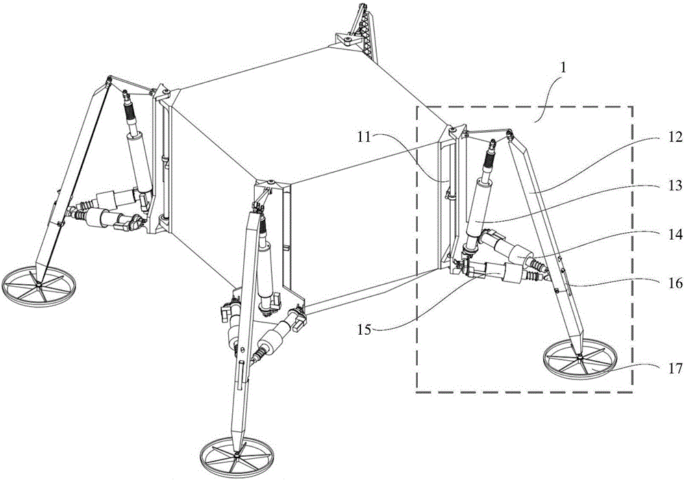
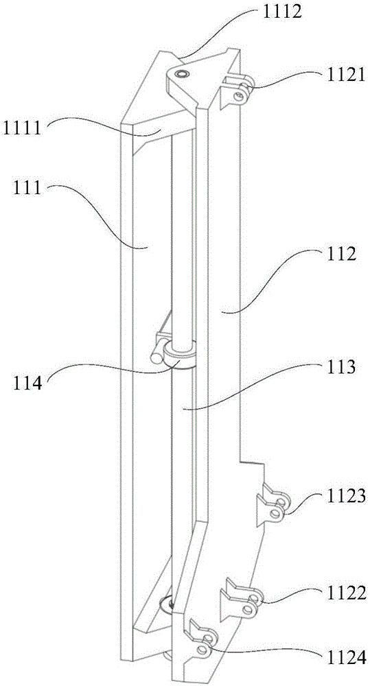
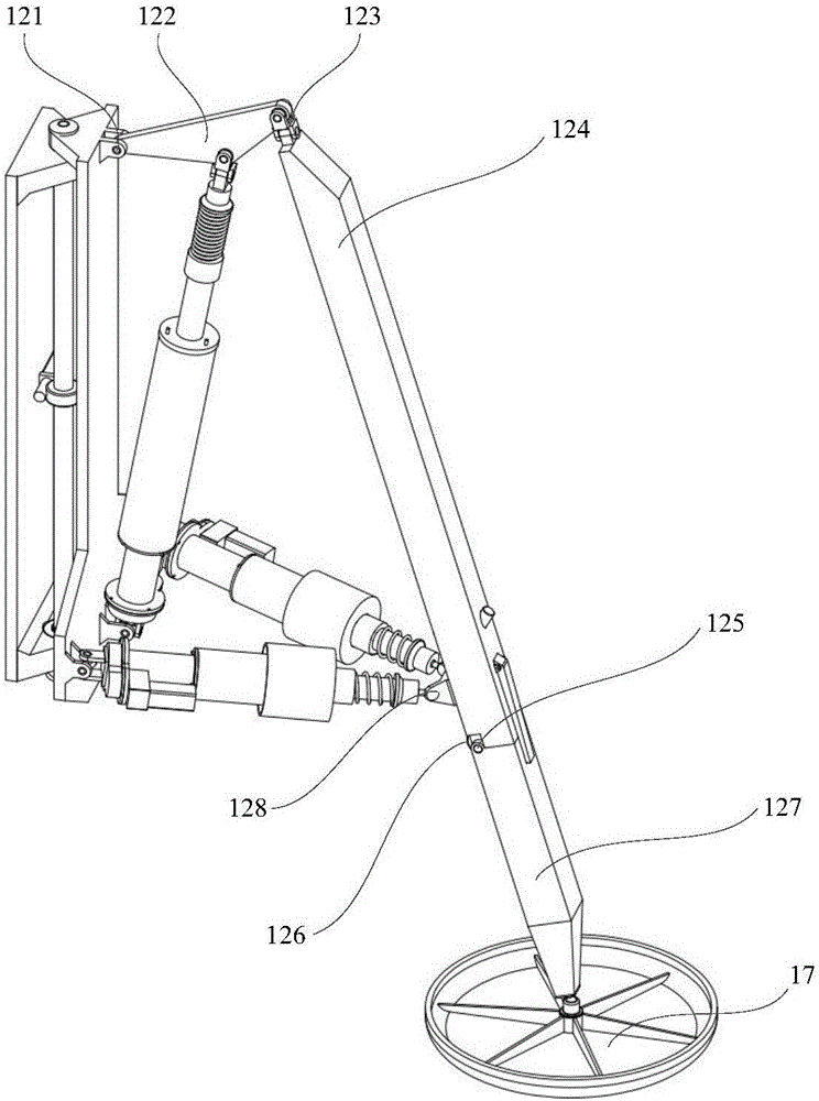
[0039] Such as figure 1 Shown here is a buffer / walking integrated lander of the present invention, which includes a lander body and the sidewall of the lander is evenly installed with several groups of buffer walking integrated mechanisms 1; the buffer walking integrated mechanism 1 includes a trunk connecting plate Assembly 11, mechanical leg assembly 12, buffer drive integrated main shock absorber 13, buffer drive integrated auxiliary shock absorber left 14, buffer drive integrated auxiliary shock absorber right 15, knee joint locking device 16 and foot ...


PUM


Abstract

The invention discloses a buffer and walking integrated landing device. Several buffer and walking integrated mechanisms are installed on the side wall of the landing device, and each buffer and walking integrated mechanism includes a body connecting plate assembly, a mechanical leg assembly, a buffering and driving integrated primary vibration reducer, buffering and driving integrated auxiliary vibration reducers, a knee joint locking device and a foot pad. Each body connecting plate assembly has the degree of freedom on medial rotation and lateral rotation; each mechanical leg assembly has the degree of freedom on the external swinging, retraction, anteflection and backward extension of hip joints, the stretching and bending of knee joints and the like; each buffering and driving integrated primary vibration reducer, each left buffering and driving integrated auxiliary vibration reducer, and each right buffering and driving integrated auxiliary vibration reducer achieve buffering or driving between the corresponding mechanical leg assembly and the corresponding body connecting plate assembly; the knee joint locking devices achieve flexible movement. The buffer and walking integrated landing device makes up for the shortcomings of a current movable landing device in the aspects of movement flexibility, use convenience and the like, and is extremely excellent in landing device body posture control capability and obstacle surmounting capability in the movement process.

Description

Technical field [0001] The invention belongs to the technical field of buffer mechanisms in the field of aerospace technology, and specifically refers to a buffer / walking integrated lander. Background technique [0002] Interplanetary exploration includes not only soft landings, but also more in-depth scientific investigations on the surface of extraterrestrial bodies. With the continuous deepening of these exploration activities, higher and higher requirements are put forward for the posture of the lander body after buffering and the detectable surface range of the extraterrestrial body. [0003] The traditional interplanetary lander is fixed at the landing site after landing buffer, and the detection range can only be expanded by releasing the patrol device it carries. Therefore, when there are unfavorable conditions such as uneven terrain in the landing area, unsatisfactory posture after landing, or the lander's buffer legs sinking on the surface of the outer star, the lander t...

Claims


Application Information

Patent Timeline
Patent Type & Authority Applications(China)
IPC IPC(8): B64G1/62
CPCB64G1/62
Inventor 贾山陈金宝居鹤华
Owner NANJING UNIV OF AERONAUTICS & ASTRONAUTICS
Why Eureka
Eureka Blog
Learn More