
Automatic take-off control strategy design of small unmanned helicopter

An unmanned helicopter and automatic take-off technology, applied in attitude control and other directions, can solve the problems of helicopter landing gear unilateral or single-point landing, sensor positioning accuracy reduction, helicopter rollover, etc.

Active Publication Date: 2015-11-11
北清通航科技(北京)有限公司
View PDF3 Cites 14 Cited by
  • Summary
  • Abstract
  • Description
  • Claims
  • Application Information

AI Technical Summary

Problems solved by technology

[0006] The second is that the automatic take-off of the helicopter needs to switch between two states. The helicopter has to enter the air flight state from the state of staying on the ground. The constraints on the helicopter in these two states are completely different. stable state, while the helicopter is a six-degree-of-freedom moving object when it is flying in the air, and it is in an unstable state, and the trim attitude of the helicopter in the air is different from the state on the ground. turn
[0007] The third is that the helicopter is affected by the ground effect in the near-ground stage, and the airflow is extremely unstable, which may easily cause the helicopter to slip, which in turn will cause a drastic change in the attitude of the helicopter, resulting in unilateral or single-point landing of the helicopter landing gear.
[0008] Fourth, since unmanned helicopters generally use GPS and other satellite navigation system sensors for position positioning, the positioning accuracy of the sensors will be reduced near the ground due to the influence of ground clutter, trees and buildings.

Method used


Image

  • Automatic take-off control strategy design of small unmanned helicopter
  • Automatic take-off control strategy design of small unmanned helicopter
  • Automatic take-off control strategy design of small unmanned helicopter

Examples


Embodiment Construction

[0069] The present invention will be further described now in conjunction with accompanying drawing. These drawings are all simplified schematic diagrams, and only illustrate the design concept of the present invention in a schematic manner.

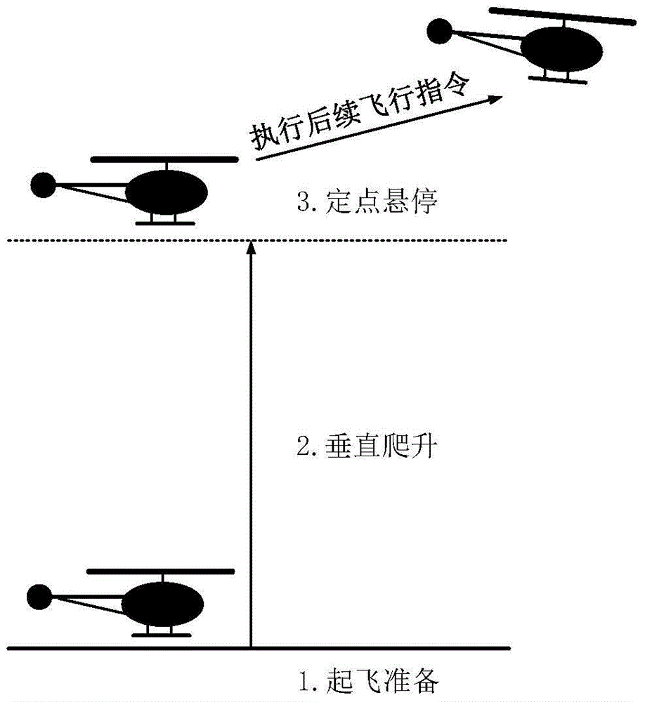
[0070] Such as figure 1 As shown, the automatic take-off process of the unmanned helicopter is divided into three stages: ground preparation, vertical climb, and fixed-point hovering:

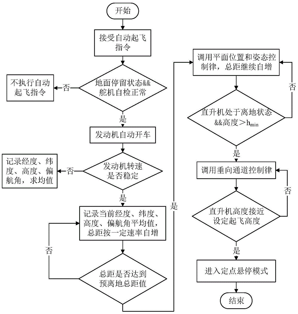
[0071] Among them, the helicopter stays on the ground during the ground preparation phase. Due to the constraints on the ground, the force on the helicopter is balanced and the state remains stable. Changes, this stage starts from the time when the helicopter receives the automatic take-off command and ends when the helicopter leaves the ground completely. The main tasks of this stage are: (1) The flight control system makes a judgment on whether to respond to the take-off command after receiving the automatic take-off control command; (2) ) If it is de...


PUM


Abstract

The invention discloses an automatic take-off control strategy design for a small unmanned helicopter, comprising steps of 1 determining whether a take-off order is responded, if yes, automatically starting up an engine and applying rotation speed stable control, 2 recording information of current longitude, height and yaw angle and solving mean values,3 if the step 2 determines that the rotation speed of the engine is stable, performing self-increscent on the collective pitch, 4 if the step 3 determines that the collective pitch reaches the pre-off-land collective pitch, performing plane position and posture control on the helicopter and continuously performing self-increment on the collective pitch until the helicopter is off the land, 5 if the step 4 determines that the helicopter is off the land, updating the collective pitch balancing value and invoking a vertical channel control law until the preset take-off height is approached, and if the step 5 determines that the take-off height is reached, and invoking a spot hovering control law to finish the take-off. The automatic take-off control strategy design for the small unmanned helicopter can improve the automatic take-off capability of the miniaturized unmanned helicopter and enhances the usage range, and is small in complexity and high in reliability.

Description

technical field [0001] The invention relates to an automatic take-off control strategy of a small unmanned helicopter. By designing the take-off process and transition strategy of the unmanned helicopter, the automatic take-off of the unmanned helicopter is realized, and belongs to the field of autonomous control of the small unmanned helicopter. Background technique [0002] A UAV is an aircraft that is controlled by radio or ground station systems and made to fly autonomously in accordance with predetermined procedures without a human driver. Compared with manned aircraft, it has significant advantages such as small size, low cost, long working hours, and can operate in dangerous and complex environments. Compared with fixed-wing aircraft, unmanned helicopters have the ability to hover in the air and move in any direction. It has the advantages of flying, ultra-low altitude and low-speed flight, and more importantly, it does not need a landing platform and a flight runway,...

Claims


Application Information

Patent Timeline
IPC IPC(8): G05D1/08
Inventor 蒙志君赵文龙陈旭智王凯鹏
Owner 北清通航科技(北京)有限公司
Learn More