Drawing die

A drawing die and die holder technology, applied in the field of special tools for stamping process, can solve the problems of increasing the tensile resistance of the blank, affecting the appearance, reducing the structural strength of the parts, etc. effect of chance

Active Publication Date: 2014-02-19
ZHEJIANG GEELY AUTOMOBILE RES INST CO LTD +1
View PDF6 Cites 21 Cited by
  • Summary
  • Abstract
  • Description
  • Claims
  • Application Information

AI Technical Summary

Problems solved by technology

[0003] During the drawing and forming process of the billet, quality defects such as wrinkling often occur due to insufficient rigidity and other reasons.
Common large-scale cladding parts, such as some parts in the roof, hood, side panels, rear doors, etc. of the car, such as the top cover, due to their simple geometry and small curvature, the blank is large at the beginning of stretching. The area is attached to the surface of the mold core, which increases the tensile resistance of the blank, resulting in insufficient stretching and insufficient rigidity; and for some other parts, such as the back door, due to the mold core shape of the drawing mold The cavity is large, and the supporting surface of the blank on the blank holder is small, so that the middle part of the blank is easy to sag under the action of its own weight, resulting in a large storage of the blank before stretching, resulting in insufficient stretching and insufficient rigidity
Insufficient stiffness will not only affect the appearance, but also reduce the structural strength of the part

Method used


Image

  • Drawing die
  • Drawing die
  • Drawing die

Examples


Embodiment Construction

[0025] In order to further explain the technical means and effects adopted by the present invention to achieve the intended invention purpose, the specific implementation, structure, features and effects of the present invention will be described in detail below in conjunction with the accompanying drawings and preferred embodiments.

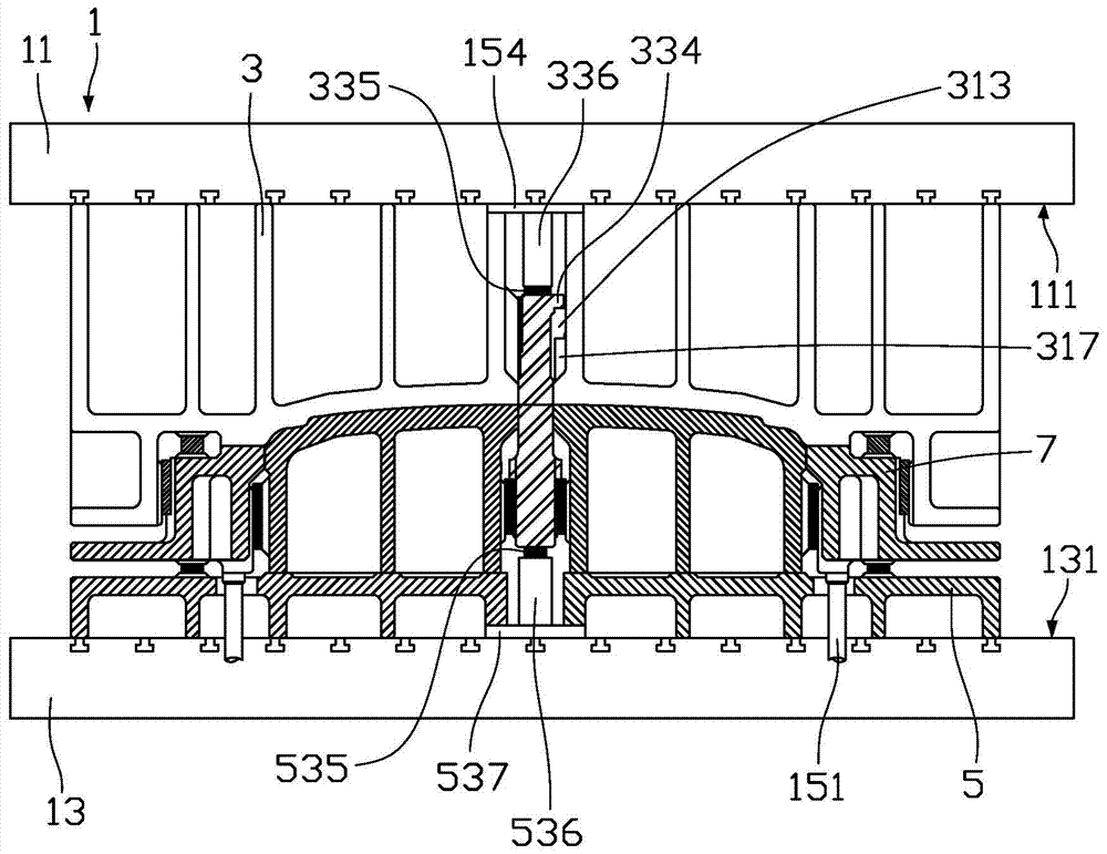
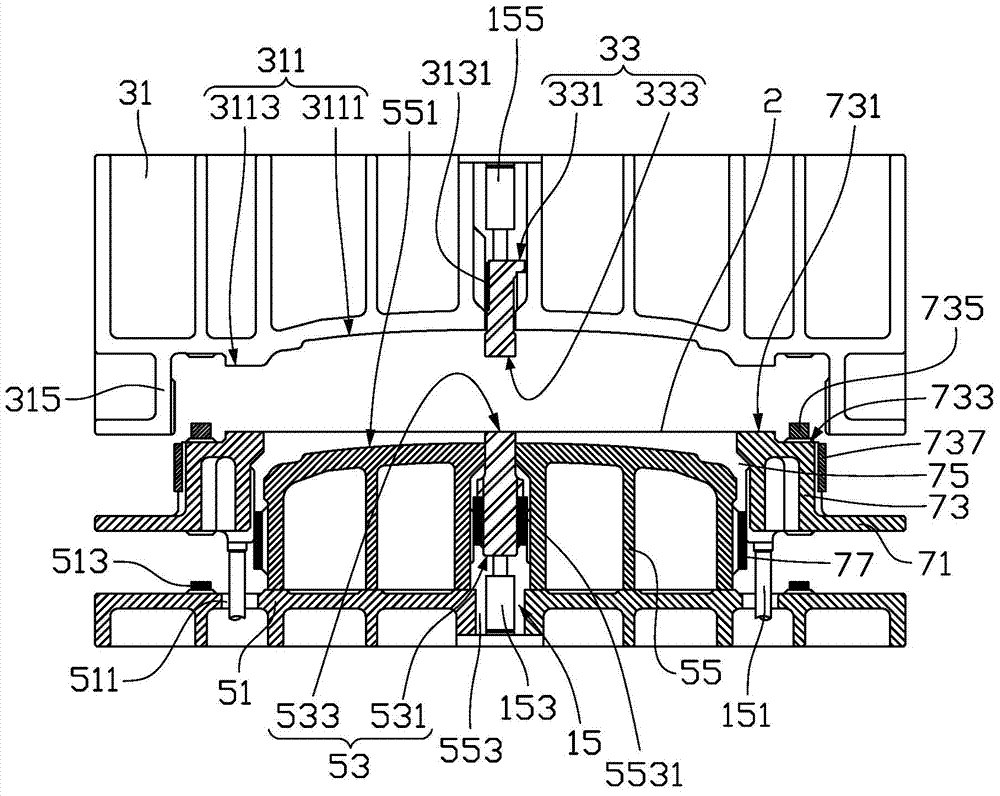
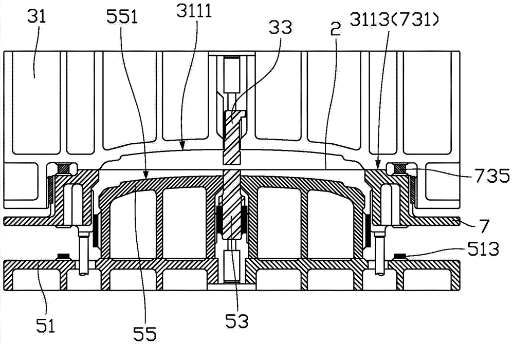
[0026] Please refer to figure 1 , the embodiment of the present invention provides a drawing die, which is used to draw the blank 2 into a desired processed part. The drawing die includes a machine platform 1 , an upper die 3 , a lower die 5 and a blank holder 7 . The blank holder 7 is used to fix the blank 2 . The machine table 1 is used to control the movement of the upper die 3 and the lower die 5, so that the upper die 3 and the lower film 5 are combined to draw the blank 2 into the parts to be processed.

[0027] Please refer to figure 2 , The machine platform 1 includes an upper machine platform 11 , a lower machine platform 13 and a d...


PUM


Abstract

A drawing die comprises an upper die and a lower die. The upper die has a forming surface used for forming parts. The lower die comprises a lower die seat, a die cavity fixed on the lower die seat and an edge pressing ring capable of sliding corresponding to the die cavity. The die cavity is provided with a die cavity surface corresponding to the forming surface. The lower die is provided with a fitting through hole passing the die cavity surface and a lower moving block capable of sliding along the fitting through hole. The edge pressing ring is sequentially located at a first position, a second position and a third position in the process of machining parts. When the edge pressing ring is located at the first position, a blank is clamped between the edge pressing ring and the upper die and contacts with the lower moving block; when the edge pressing ring moves from the first position to the second position, the lower moving block presses against the blank and performs pre-drawing on the blank; when the edge pressing ring moves from the second position to the third position, the lower moving block moves downwards, the die cavity draws the blank formally. The lower moving block can support and hold the blank, and defects of wrinkling and insufficient stiffness caused by blank gravity when large-scale parts are stamped can be prevented.

Description

technical field [0001] The invention relates to the field of special tools for stamping technology, in particular to a drawing die. Background technique [0002] Existing drawing dies include upper die, lower die and blank holder. The upper mold and the lower mold respectively include an upper mold core and a lower mold core. The upper mold core is used to surround the lower mold core to form a cavity consistent with the part to be drawn. The blank holder is usually located on the lower film and is used to fix the blank used for drawing. When stamping and forming, the upper mold moves toward the lower mold, and clamps the edge of the blank between the upper mold and the blank holder; then, the upper mold continues to move downward, and together with the lower film, the rest of the blank Press it into the cavity formed between the upper film core and the lower mold core, and draw the blank into the parts to be processed. [0003] During the drawing and forming process of ...

Claims


Application Information

Patent Timeline
Patent Type & Authority Applications(China)
IPC IPC(8): B21D37/10
Inventor 谭植文邓劲松魏宪波韦兴民冯擎峰
Owner ZHEJIANG GEELY AUTOMOBILE RES INST CO LTD
Why Eureka
Try Eureka