Panel Mount Connector

A connector and panel technology, applied in the direction of connection, connection component installation, two-component connection device, etc., can solve problems such as reduction of tensile force resistance, falling off, etc., to achieve enhanced tensile resistance, deformation prevention, efficient and easy fixing operation Effect

Inactive Publication Date: 2017-04-12
HONDA TSUSHIN IND
View PDF6 Cites 0 Cited by
  • Summary
  • Abstract
  • Description
  • Claims
  • Application Information

AI Technical Summary

Problems solved by technology

Thereby, the resistance to the tensile force of the coaxial connector 21 and the circular contact 22 is reduced, and there is a possibility of falling off the board or the case 24.

Method used


Image

  • Panel Mount Connector
  • Panel Mount Connector
  • Panel Mount Connector

Examples


Embodiment 1

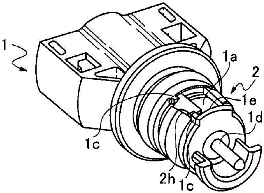
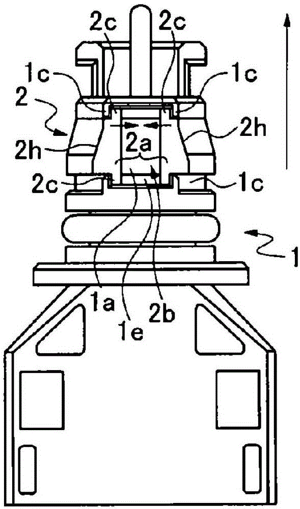
[0039] Figure 1A˜2C show the panel mount connector 1 in Embodiment 1 of the present invention, and the connector 1 has a groove 1 a formed over the entire circumference of the cylindrical portion on the front end side. An annular locking piece 2 formed of an elastic member is fitted and fitted into this groove 1a.

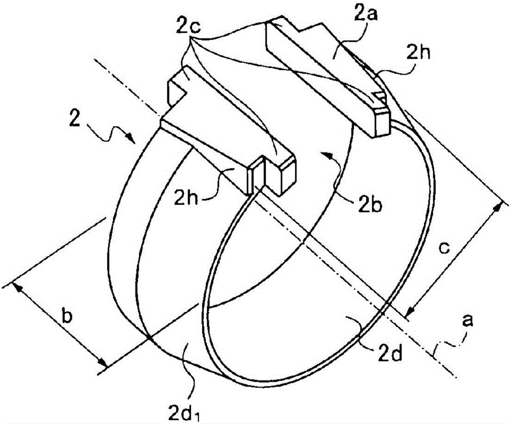
[0040] The locking piece 2, such as Figure 1C As shown, there is an annular body part 2d formed by cutting off a part of the circumference. The outer peripheral surface of the main body portion 2d has an inclined surface 2d whose diameter becomes smaller toward the front end side. 1 . Protrusions 2a protruding upward are respectively formed at both end edges of the body portion 2d facing across the notch portion 2b formed by cutting out a part of the circumference. Protruding portions 2c protruding in the direction of the axis a of the main body portion 2d are respectively provided at both ends of the protruding portion 2a.

[0041] In addition, a total of f...

Embodiment 2

[0048] Figure 3A-3D This panel mounting connector 1 in Embodiment 2 of the present invention is shown. This connector 1 is the same as the first embodiment except that the locking piece 2e to be mounted in the groove 1a formed in the cylindrical portion on the front end side is different, so repeated description of the same parts will be omitted.

[0049] On the locking piece 2e, such as Figure 3C As shown, the protruding portion 2a is formed through the extending portion 2f extending upward with the width b of the main body portion 2d. Furthermore, protruding portions 2c protruding from a part of both ends of the protruding portion 2a in the axial direction of the locking piece 2e are formed. In the locking piece 2e, the width c between the circumferential outer wall surfaces of the extending portions 2f and 2f facing each other in the enlarged diameter state is the same as Figure 3B The width D between the pair of partition walls 1c, 1c formed in the circumferential di...


PUM


Abstract

The invention provides a panel mounting connector, possessing a connector body and an annular stop piece, wherein the connector body possesses a groove formed by the cylindric part of an installation hole inserted into an installation object component; the stop piece is installed in the groove in order to avoid separating from the installation hole and possesses an annular body, the annular body having a cutting opening used for cutting part of a periphery for separation. At two opposite end edge parts of the body, projecting parts projecting from the end surface the body to the axial direction at the end part in the axial direction of the body are respectively arranged; at the positions of the groove corresponding with the projecting parts of the stop piece, a pair of separating walls used for limiting the projecting parts from moving in peripheral directions are arranged; an accepting part used for allowing free movement of the projecting parts in peripheral directions is formed between the separating walls; in the accepting part, a step part is arranged adjacent to the separating walls to allow each projecting part of the stop piece to respectively rise to be clamped. A hanging part formed by the stop card exists on a whole periphery, which can enhance stretching resistance of deformation force and avoid the stop piece from being pulled out.

Description

technical field [0001] The present invention relates to a panel mounting connector which is mounted in a connector mounting hole of a board forming a box in a solar power generation device or the like installed outdoors while maintaining watertightness. Background technique [0002] As the board mounting method of the existing panel mount connector, known, in such as Figure 11A , 11B In the board fixing method in the coaxial connector 21 and the circular contact 22 of the circular board mounting connector shown, such as Figure 12A , 13A As shown, in order to prevent the contact from being pulled out after the above-mentioned contact is installed in the mounting hole of the board, the retractable locking piece 23 fitted into the annular groove 21a, 22a is used to form a single-press type. Techniques for locking methods. The above-mentioned locking piece 23, such as Figure 11C As shown, it has a ring shape with a part of the ring cut away, and has a tapered portion 23a ...

Claims


Application Information

Patent Timeline
Patent Type & Authority Patents(China)
IPC IPC(8): H01R13/74H01R13/639H01R24/38
Inventor 大阿久清志
Owner HONDA TSUSHIN IND
Why Eureka
Try Eureka