
Method of making elastic laminate

Laminate, elastic technology, used in the field of manufacturing elastic laminates

Active Publication Date: 2014-12-31
MONDI GRONAU
View PDF7 Cites 0 Cited by
  • Summary
  • Abstract
  • Description
  • Claims
  • Application Information

AI Technical Summary

Problems solved by technology

However, it is not possible to manufacture laminates with adjacent elastic and non-elastic sections in the longitudinal direction of the web using said method

Method used


Image

  • Method of making elastic laminate

Examples


Embodiment Construction

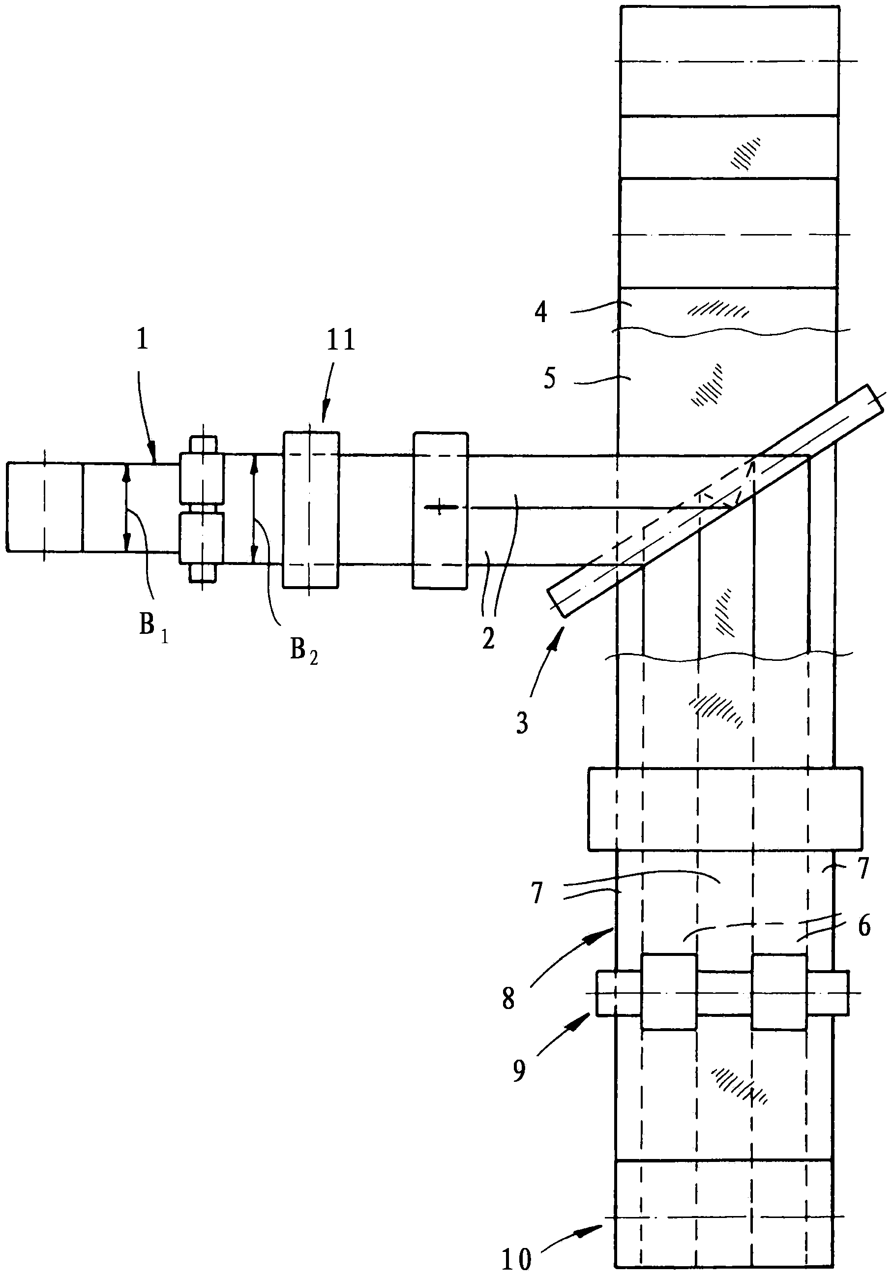
[0019] In the method shown in the figure, an elastic film 1 is stretched transversely to the web direction in a preactivation station 11 and cut into strips 2 after elastic relaxation. The strips 2 are guided via a deflector 3 and are laminated side by side between two nonwoven material webs 4 and 5 as parallel strips. The material webs 4 and 5 are guided without pretensioning above and below the strip 2 and are adhesively or thermally bonded to the strip 2 . The view clearly shows that the elastic strips 2 are laminated between the covering layers at a distance from one another and that the nonwoven covering layers 4 and 5 are directly bonded together in the interstices between the elastic strips 2 . Elastic regions 6 and inelastic regions 7 are thus formed in the laminate 8 . The laminate is supplied to an activation unit 9 in which the laminate 8 is stretched transversely to the web direction in the region 6 rendered elastic by the laminated strip 2 . After elastic relaxa...


PUM


Abstract

The invention relates to a method of making an elastic laminate. According to the invention, an elastic film (1) is stretched transverse to the web direction and, after elastic relaxation, is cut into strips (2). The strips (2) are then laminated next to one another between nonwoven material webs (4, 5) supplied without prestretching and joined to the strips (2). Last, the laminate (8) thus formed is stretched transverse to the web direction in regions (6) rendered elastic by the laminated strips (2) and, after elastic relaxation, is wound into a roll (10). - One figure

Description

technical field [0001] The present invention relates to a method of manufacturing an elastic laminate. [0002] The invention relates to a method in which elastic strips are laminated side by side between nonwoven material webs. The nonwoven material web is provided without pretensioning and bonded to the strip. The laminate formed in this way is then stretched transversely to the web direction in the region rendered elastic by the laminated strip and, after elastic relaxation, wound into a roll. Due to the stretching, also called mechanical activation, of the laminate, the elastic properties of the laminate are improved transversely to the web direction (CD direction) of the material web. Background technique [0003] A method of this character is known, for example, from EP1686209. Elastic elements for hygiene products, in particular elastic closure strips for diapers, each having an elastic central region and less elastic portions at both ends, can be punched from the ...

Claims


Application Information

Patent Timeline
IPC IPC(8): B32B37/30
CPCA61F13/15593A61F13/4902B32B5/022B32B27/12B32B27/285B32B27/302B32B27/32B32B27/40B32B37/144B32B38/0004B32B2307/51B32B2555/02
Inventor D·霍莫勒M·舍恩贝克
Owner MONDI GRONAU
Learn More