LED display screen seam correcting method

An LED display and display technology, applied in static indicators, instruments, etc., can solve the problems of LED module lamp bead position offset error, inaccurate correction brightness coefficient, LED lamp bead spacing error, etc.

Inactive Publication Date: 2018-10-09
上海诣阔软件有限公司
View PDF6 Cites 32 Cited by
  • Summary
  • Abstract
  • Description
  • Claims
  • Application Information

AI Technical Summary

Problems solved by technology

[0005] However, the above-mentioned technology still has defects and errors, as follows (1) In order to obtain the effective lamp bead brightness, it is necessary to take multiple images with the camera and integrate the brightness coefficient. At the same time, there is jitter during the shooting process, and the position of the LED module lamp bead will shift. Therefore, there is also an error in the LED lamp bead spacing obtained by integrating the image brightness coefficient, and the corrected brightness coefficient is relatively inaccurate; (2) Due to the unknown situation of the LED display splicing module unit, it is possible to obtain the LED lamp bead through the algorithm The brightness effective area difference is greater than the actual module lamp bead spacing, and the calculated brightness correction coefficient also corrects the position of the splicing gap, resulting in uneven brightness of the final corrected screen; (3) If the LED display screen The bigger the camera is to take effective pictures, the distance between the camera and the LED display screen needs to be enlarged, and a larger step size (X*X) needs to be taken for image shooting, resulting in more RGBxyz related images (X*X) ); this process will also have the problems in the above (2), which will cause the image position to shift, and the resulting error will be even greater

Method used


Image

  • LED display screen seam correcting method
  • LED display screen seam correcting method
  • LED display screen seam correcting method

Examples


Embodiment 1

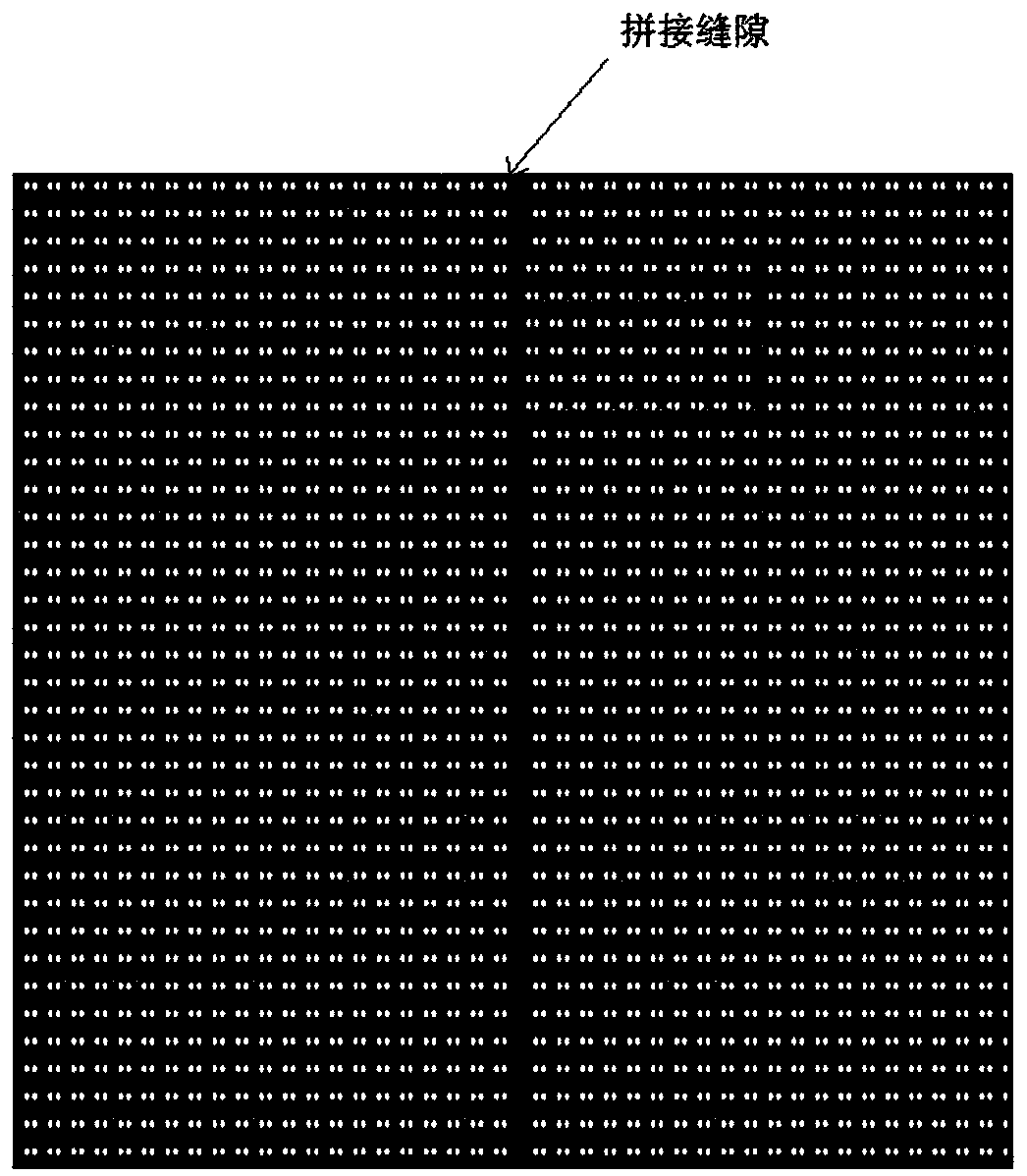
[0040] refer to Figure 1-Figure 5b As shown, the present invention provides a method for correcting LED display seams, comprising the following steps:

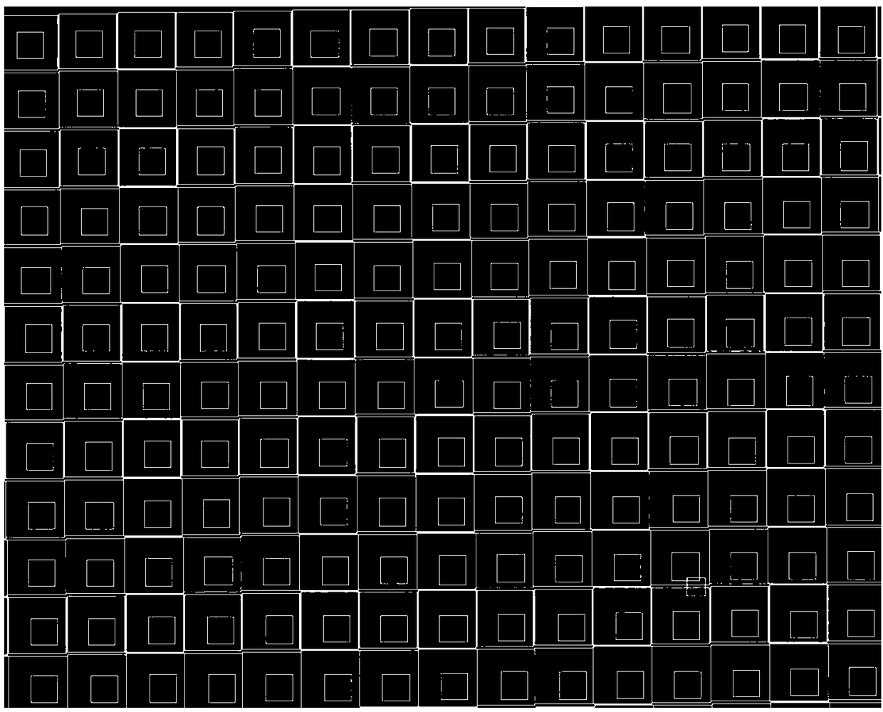
[0041] Step (1): Determine the size of the bright and dark line areas that the splicing units of the splicing display module are alternately arranged in the X and Y axis directions, wherein step (1) includes: Step (1.1): according to the splicing of the LED display module The position of the bright and dark lines formed by the full screen divides the entire spliced ​​LED display module into different equal areas according to the principle of uniform distribution; step (1.2): determine the splicing display according to the size of the splicing unit that divides the adjacent display module areas in the spliced ​​display The splicing units of the screen module are arranged alternately in the X and Y axis directions of the bright and dark line areas, where the X and Y axis directions are the directions of the splicing gaps betwee...

Embodiment 2

[0050] The steps of a splicing bright and dark line correction method: ① determine the selected splicing display splicing unit and adjacent splicing units in the X / Y axis direction according to the size of the selected splicing display splicing unit and adjacent splicing units The size of multiple divided area module units that are repeatedly arranged, each of which includes multiple display module units; A plurality of display units at the designated X / Y coordinate positions of each of the multiple division area modules for the selected mosaic display screen splicing unit and the adjacent splicing unit to obtain the shooting target image , where the specified X / Y coordinate position of the selected splicing display splicing unit is a display bright block composed of a plurality of display module units; ④ Calculate the brightness correction coefficient of each edge display unit of the splicing gap between the specified selected splicing display screen splicing unit and adjacen...


PUM


Abstract

The invention provides an LED display screen seam correcting method. The method comprises the steps that (1) the size of bright and dark line regions, which are alternately arranged in X and Y axis directions, of spliced units of spliced display screen modules is determined; (2) camera shooting is carried out on the size of domain spliced units in the display screen module areas to acquire a target image; (3) the target image is processed to acquire the gray level of the spliced display screen module areas; (4) the brightness correction coefficient of each edge display screen module of splicing gaps which divide adjacent display screen module areas in a spliced display screen is calculated, and the coefficient is, as a reference, for supplementing and correcting the splicing gaps of the display screen which lead to brightness errors of spliced bright and dark lines; and (5) the module lamp bead spacing of bright blocks of the spliced display screen and the spacing of the splicing gapsof the display screen modules are calculated, and through the acquired difference between two spacings, the brightness coefficient of edge module units of adjacent splicing gaps is adjusted accordingto the effective brightness ratio coefficient, so as to correct LED display screen seams.

Description

technical field [0001] The invention relates to the technical field of LED display screen control, in particular to a method for correcting LED display screen seams. Background technique [0002] LED display screens are usually spliced ​​by multiple LED display modules. During the splicing process of LED display screens, there are limitations such as manual machining and assembly technology. The splicing between the splicing units of LED display The distance between the edges of the display module lamp beads is inconsistent. During the display process, dark lines will appear when the edge spacing of the LED display module lamp beads is greater than the standard spacing of the display module, and bright lines will appear when the edge spacing of the LED display module lamp beads is smaller than the standard spacing of the display module, forming The dark lines or bright lines are collectively referred to as LED display splicing bright and dark lines in the industry. [0003...

Claims


Application Information

Patent Timeline
Patent Type & Authority Applications(China)
IPC IPC(8): G09G3/32
CPCG09G3/32G09G2320/0233
Inventor 江旭吴国荣吴小国
Owner 上海诣阔软件有限公司
Why Eureka
Try Eureka