Splicing bright-dark line correction method

A bright and dark line, splicing technology, applied in the direction of instruments, static indicators, etc., can solve the problems of inaccurate correction coefficient, uneven screen body, LED light point spacing error, etc., to reduce calculation errors and avoid calculation inaccuracy. Effect

Active Publication Date: 2015-09-16
XIAN NOVASTAR TECH
View PDF5 Cites 44 Cited by
  • Summary
  • Abstract
  • Description
  • Claims
  • Application Information

AI Technical Summary

Problems solved by technology

[0005] However, for the aforementioned prior art, (a) it needs to take multiple images and then combine them into one. Due to the camera shake in the process of taking the picture, the position of the LED light point will be offset, so the combined image is obtained There is an error in the spacing of the LED lights, and the calculated correction coefficient is not accurate; (b) Since the size of the splicing unit is unknown, as long as the difference in the area of ​​the two LED lights is greater than a certain threshold, it is considered that there is a gap and corrected / corrected, Therefore, the position without splicing gap will also be repaired, resulting in uneven screen body after correction; (c) the larger the LED display screen, the farther the camera is required from the screen body, and a larger spacing point is required at this time (such as K*K) for image capture, so more images need to be captured (K*K); in addition, there is camera shake in the process of capturing images, the image position will be shifted, and the error introduced will be larger

Method used


Image

  • Splicing bright-dark line correction method
  • Splicing bright-dark line correction method
  • Splicing bright-dark line correction method

Examples


no. 1 example

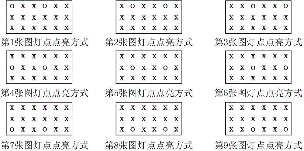
[0033] See Figure 2 to Figure 6 The splicing bright and dark line correction method suitable for a spliced ​​display such as an LED display provided by the first embodiment of the present invention can be realized by the following technical solution. specifically:

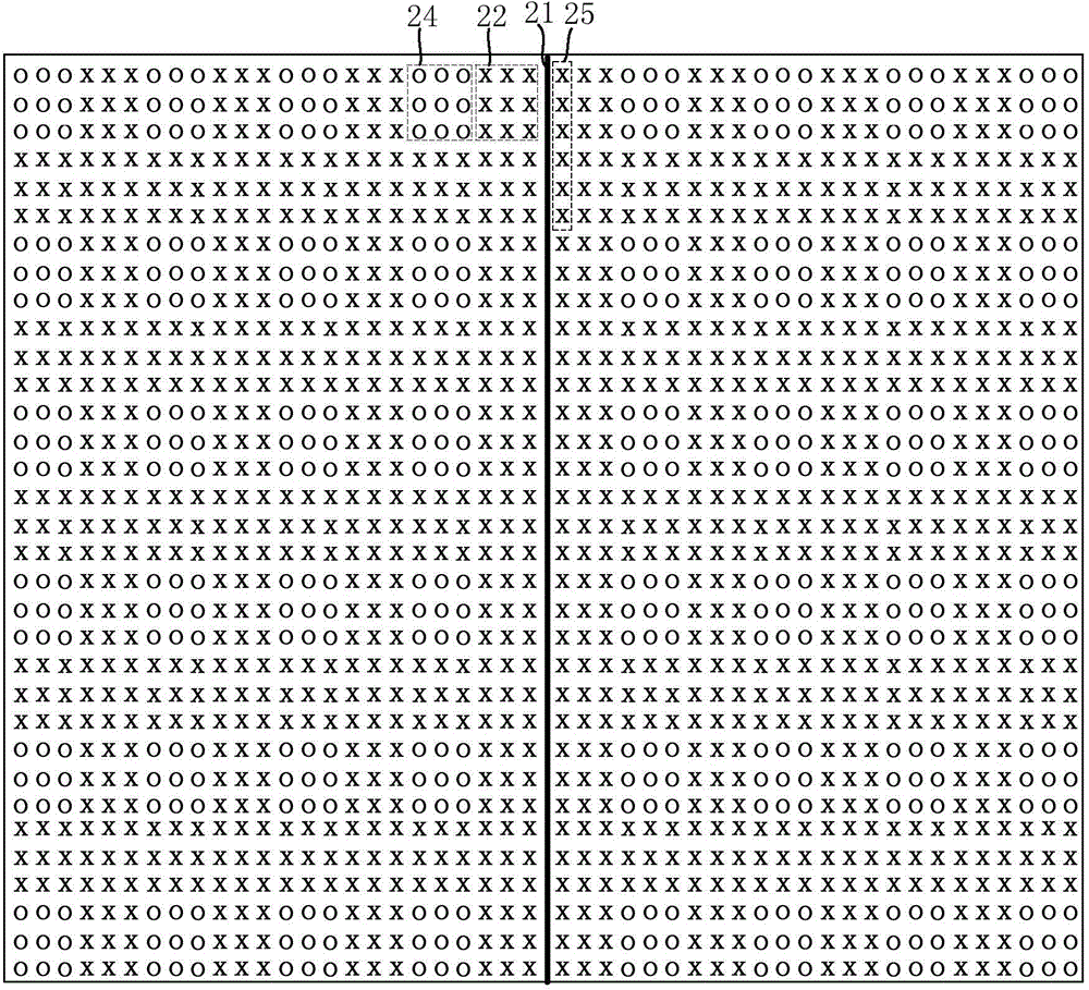
[0034] First, according to the size of the splicing unit of the target LED display, calculate the lighting mode of the screen LED light point of the target LED display, that is, the lighting mode of the screen display unit, because the splicing unit ( figure 2 The size of two adjacent splicing units shown in ) is known (taking a rectangular splicing unit as an example, its size is the number of LED pixels in the row and column direction), so the position of the splicing gap in the captured image can be clearly known. In this embodiment, for each row of display blocks containing bright blocks, for example, on both sides of the splicing between the splicing units, the dark blocks 22, 22, 3×3 display bright blocks...

no. 2 example

[0045] See Figure 7 to Figure 11 The splicing bright and dark line correction method suitable for a spliced ​​display such as an LED display provided by the second embodiment of the present invention can be realized by the following technical solution. specifically:

[0046] First, according to the splicing unit size of the target LED display, calculate the lighting mode of the LED light points of the target LED display screen, that is, the lighting mode of the screen display unit. Since the stitching unit ( Figure 7 The size of two adjacent stitching units shown in ) is known, so the position of the stitching gap in the captured image can be clearly known. In this embodiment, for each row of display blocks containing bright blocks, for example, the mosaic unit on the left side of the mosaic gap 71 displays dark blocks 72 in 5×3 and bright blocks 74 in 3×3 along the direction away from the mosaic gap 71 Arranged alternately, the splicing units on the right side are arrang...


PUM


Abstract

The invention relates to a splicing bright-dark line correction method which is applicable to splicing type display screens such as an LED screen. The splicing bright-dark line correction method comprises the steps of determining the size of each display bright block and the size of each display dark block according to the size of splicing units, then controlling and lightening the display screen so as to be provided for shooting to acquire a target image; carrying out image processing on the target image so as to acquire the gray scale center of each of the plurality of bright blocks, and then calculating the display unit spacing and the splicing gap spacing; and finally, calculating a correction coefficient of each marginal display unit, which is adjacent to a splicing gap, of the splicing units by using the display unit spacing and the splicing gap spacing so as to be used for correcting a bright-dark line caused by the splicing gap. According to the invention, people can carry out correction on the bright-dark line accurately by only shooting one image through designing the display unit lightening mode; and furthermore, a problem that the display body uniformity get poor because bright-dark line correction in the prior art is carried out through full-screen analysis can also be avoided.

Description

technical field [0001] The invention relates to the technical field of display control, in particular to a splicing bright and dark line correction method. Background technique [0002] LED displays are usually spliced ​​by multiple splicing units. Due to the limitations of machining accuracy and assembly accuracy in the splicing process, the splicing between the splicing units is not uniform, resulting in LED lights of the same color on the edge of the splicing. Inconsistent dot spacing. When displaying an image, a dark seam will appear when the spacing is greater than the standard spacing of the light points, and a bright seam will appear when the spacing is smaller than the standard spacing of the light points. dark line. [0003] It is difficult to completely solve the splicing bright and dark lines caused by machining, etc. by improving the precision of machining. The traditional method observes the position of spliced ​​bright and dark lines with human eyes, and man...

Claims


Application Information

Patent Timeline
Patent Type & Authority Applications(China)
IPC IPC(8): G09G3/32
Inventor 袁胜春杨树林
Owner XIAN NOVASTAR TECH
Why Eureka
Try Eureka