
Rotation position estimating device for synchronous motor and rotation position estimating method

A technology of synchronous motor and rotation position, which is applied in the estimation/correction of motor parameters, motor control, AC motor control, etc., and can solve the problems that the 180-degree power-on method cannot be applied

Active Publication Date: 2018-10-09
KK TOSHIBA +1
View PDF15 Cites 0 Cited by
  • Summary
  • Abstract
  • Description
  • Claims
  • Application Information

AI Technical Summary

Problems solved by technology

[0008] However, in Patent Document 1, since the 120-degree energization method is assumed, it cannot basically be applied to a 180-degree energization method for phases that do not generate a non-energized state.

Method used


Image

  • Rotation position estimating device for synchronous motor and rotation position estimating method
  • Rotation position estimating device for synchronous motor and rotation position estimating method
  • Rotation position estimating device for synchronous motor and rotation position estimating method

Examples


Embodiment Construction

[0022] Therefore, there are provided a rotational position estimation device for a synchronous motor and a rotational position estimation method for a synchronous motor that are compatible with a wider range of energization methods.

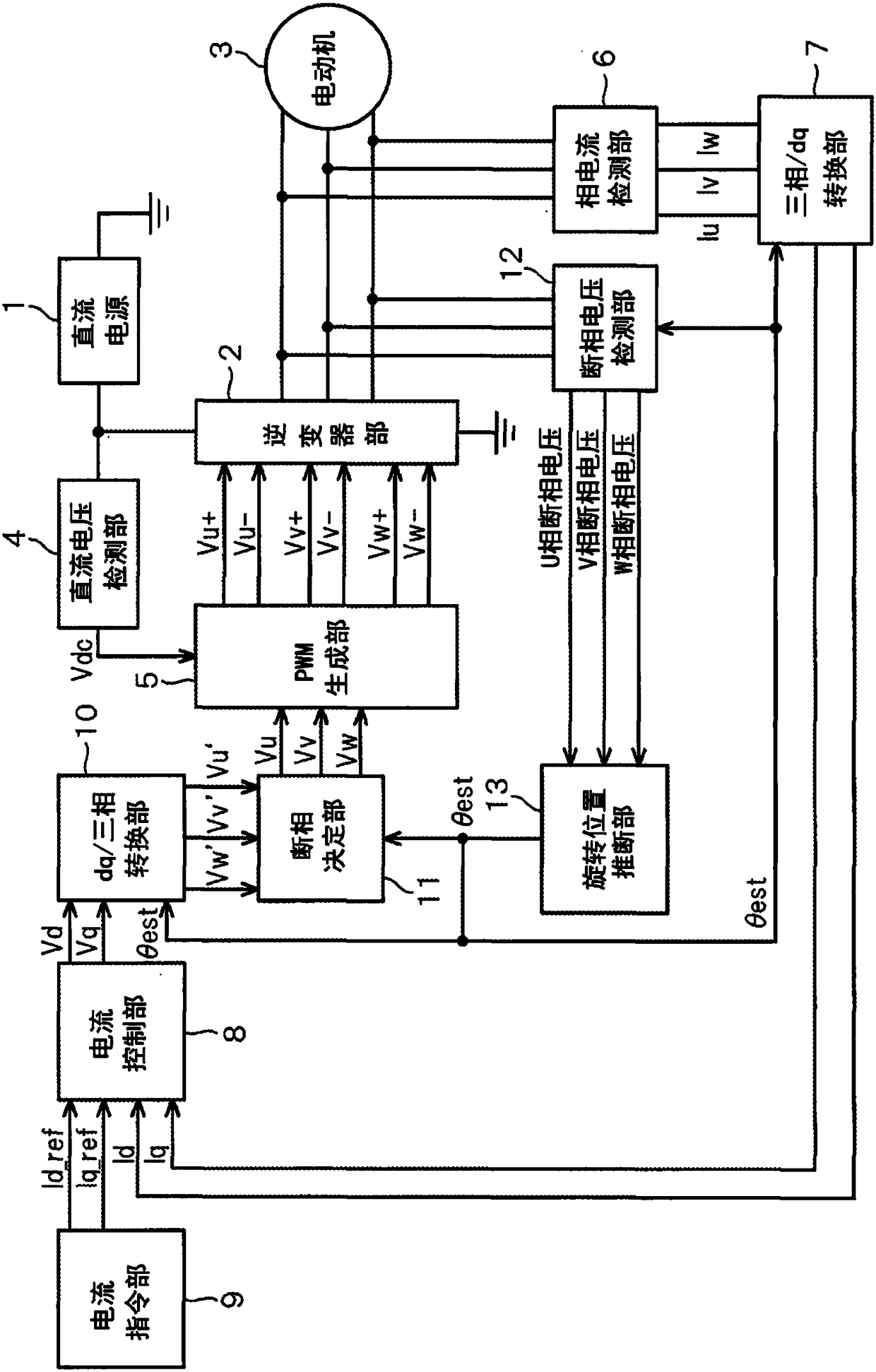
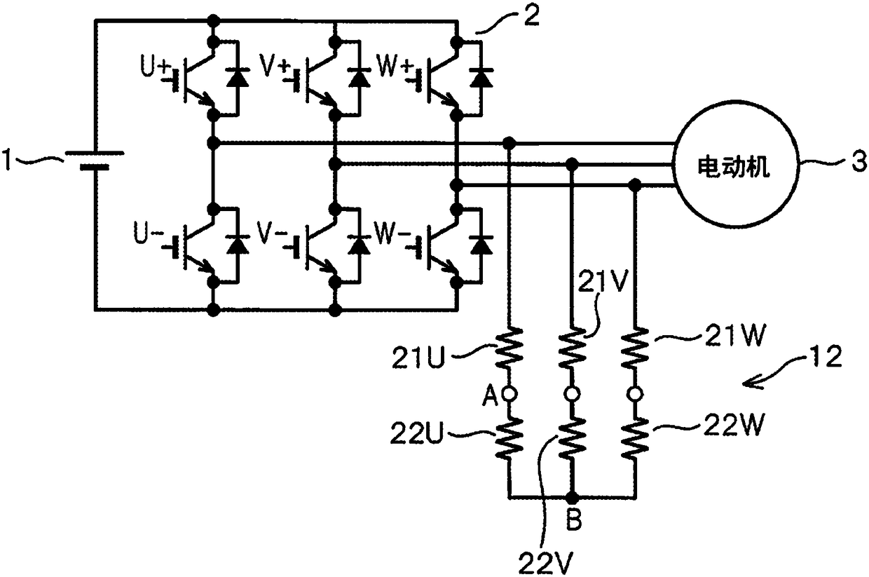
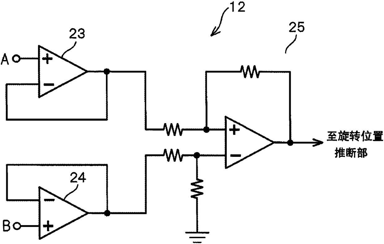
[0023] The rotational position estimating device of a synchronous motor according to the embodiment includes: an open-phase generation unit configured to set any one of the three phases to a negative state for an inverter connected to a three-phase synchronous motor and constituted by a plurality of switching elements. The energized state is used as the open phase; the open phase determination part determines which phase is used as the above open phase; the open phase voltage storage part detects the voltage of the above open phase; the open phase voltage storage part stores the above voltage; the voltage zero point push part, according to A zero point of the voltage is estimated from the open phase voltage stored in the open phase voltage storage...


PUM


Abstract

According to the rotational position estimating device and the rotational position estimating method of the synchronous motor provided by the embodiment, the rotational position estimating device includes an open phase generating unit that sets any one of the three phases to a non-energized state as an open phase for an inverter connected to a three-phase synchronous motor and composed of a plurality of switching elements; an open phase determination unit that determines which phase is to be taken as the open phase; an open phase voltage detection unit that detects a voltage of the open phase;an open phase voltage storage unit storing the voltage; a voltage null estimation unit that estimates a null point of the voltage based on the open phasevoltage stored in the open phase voltage storage unit; and a position estimation unit that estimates a rotational position of the motor based on the null point.

Description

technical field [0001] Embodiments of the present invention relate to an apparatus and method for estimating the rotational position of a synchronous motor. Background technique [0002] Conventionally, detection of a rotational position has been performed in order to appropriately control a motor. The detection of the rotational position refers to the detection of the electrical angle phase which is the position on the electrical angle coordinates of the motor. Some methods use position sensors such as rotary encoders (rotary encoders), resolvers (resolvers), and Hall elements to detect the rotational position. However, there are cases where the position sensor cannot be provided due to product cost, structural constraints, and the like. [0003] Therefore, a method of estimating the rotational position from current or voltage information without using a position sensor is implemented. Types of this method include, for example, an induced voltage utilization type and an ...

Claims


Application Information

Patent Timeline
Patent Type & Authority Applications(China)
IPC IPC(8): H02P23/14
CPCH02P6/18H02P23/14H02P2207/05H02P25/024
Inventor 柴野勇介前川佐理久保田寿夫吴梦悦
Owner KK TOSHIBA
Learn More