Method and device for triggering buffer status report and terminal
A technology of buffer state and trigger device, applied in the field of communication engineering, to achieve the effect of effectively allocating resources and meeting QoS requirements
- Summary
- Abstract
- Description
- Claims
- Application Information
AI Technical Summary
Problems solved by technology
Method used
Image
Examples
Embodiment 1
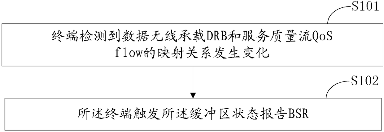
[0048] image 3 is a flow chart of the method for triggering the buffer status report provided by the first embodiment of the present invention, such as image 3 As shown, the trigger methods of the buffer status report include:
[0049] Step S101: The terminal detects that the mapping relationship between the data radio bearer DRB and the quality of service flow QoS flow has changed;
[0050] Step S102: the terminal triggers the buffer status report BSR.
[0051] According to the above triggering method, the terminal judges whether to trigger BSR by detecting whether the mapping relationship between DRB and QoS flow changes. This BSR triggering method can enable the base station to know in time the information that the terminal will send in the flow-based QoS architecture. BSR (that is, the detailed information of the data to be sent by the terminal), which can allocate resources more effectively and meet different QoS requirements of different services.
[0052] The imple...
Embodiment 2
[0075] This embodiment is a specific implementation of the buffer status report triggering method based on the first embodiment. The terminal establishes a connection with cell 1, and two data radio bearers (DRBs) are configured, which are data radio bearers 1 (DRB1 ) and data radio bearer 2 (DRB2), and notify the terminal to obtain the mapping relationship between DRB and QoS flow through the reflection method.
[0076] The corresponding relationship between the DRB and the assigned LC and LCG is shown in the following table:
[0077] radio bearer
Attributed LC
Affiliated LCG
3
0
4
1
[0078] Step 1: At the second moment, the terminal detects the downlink data packet of DRB1, parses out that the QoS flowID in the data packet is 1, and generates a mapping relationship between DRB and QoS flow, and the terminal detects the downlink data packet of DRB2, and parses out that the data packet con...
Embodiment 3
[0095] This embodiment is a specific implementation of the method for triggering the buffer status report based on the first embodiment. The terminal establishes a connection with cell 2 and is configured with two data radio bearers (DRBs), which are respectively data radio bearers 1 (DRB1 ) and data radio bearer 2 (DRB2), and notify the terminal to obtain the mapping relationship between the data radio bearer and the QoS flow through the reflection method.
[0096] The corresponding relationship between the DRB and the assigned LC and LCG is shown in the following table:
[0097] radio bearer
Attributed LC
Affiliated LCG
Data Radio Bearer 1
3
0
Data Radio Bearer 2
4
1
[0098] Step 1: At the second moment, the terminal detects the downlink data packet of DRB1, parses out that the QoS flow ID contained in the data packet is 1, and the contained QoS flow ID is 2, generates a mapping relationship between DRB and QoS flow, and the t...
PUM
 Abstract
Description
Claims
Application Information
 - R&D
- Intellectual Property
- Life Sciences
- Materials
- Tech Scout
- Unparalleled Data Quality
- Higher Quality Content
- 60% Fewer Hallucinations
Browse by: Latest US Patents, China's latest patents, Technical Efficacy Thesaurus, Application Domain, Technology Topic, Popular Technical Reports.
© 2025 PatSnap. All rights reserved.Legal|Privacy policy|Modern Slavery Act Transparency Statement|Sitemap|About US| Contact US: help@patsnap.com


