A mobility management method and device

A management method and mobility technology, applied in the field of communication, can solve problems that have not yet proposed effective solutions and cannot be applied

Active Publication Date: 2022-07-19
ZTE CORP
View PDF4 Cites 0 Cited by
  • Summary
  • Abstract
  • Description
  • Claims
  • Application Information

AI Technical Summary

Problems solved by technology

Since the handover between networks in related technologies does not involve the new state in LTE and 5G new RAT, it cannot be applied in this scenario
For the problem of mobility management between LTE and 5G base stations under the new state of RRC of LTE and 5G, no effective solution has been proposed in related technologies

Method used


Image

  • A mobility management method and device
  • A mobility management method and device
  • A mobility management method and device

Examples


Embodiment 1

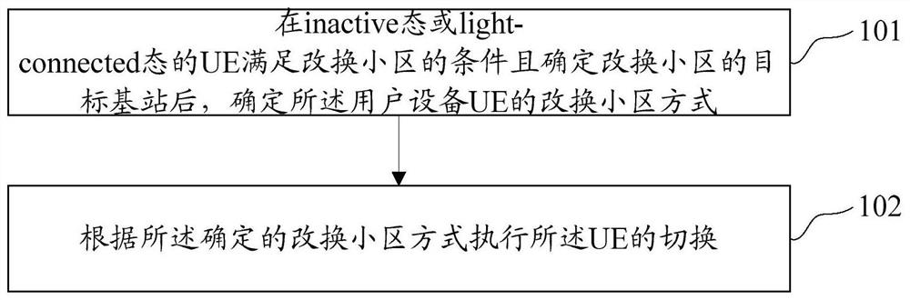
[0167] A mobility management method such as figure 1 shown, can include:

[0168] Step 101, after the UE in the inactive state or the light-connected state satisfies the conditions for changing the cell and determines the target base station for changing the cell, determine the way of changing the cell for the UE;

[0169] Step 102, performing handover of the UE according to the determined cell changing mode;

[0170] Wherein, the way of changing the cell of the UE includes at least one of the following: maintaining the user plane link of the UE to the source base station; transferring the user plane link of the UE to the target base station.

[0171] In practical applications, the foregoing method in this embodiment may be implemented by the source base station. In practical applications, the target base station satisfies one of the following: the radio access technology RAT to which it belongs is of the same type as the source base station; the radio access technology RAT ...

Embodiment 2

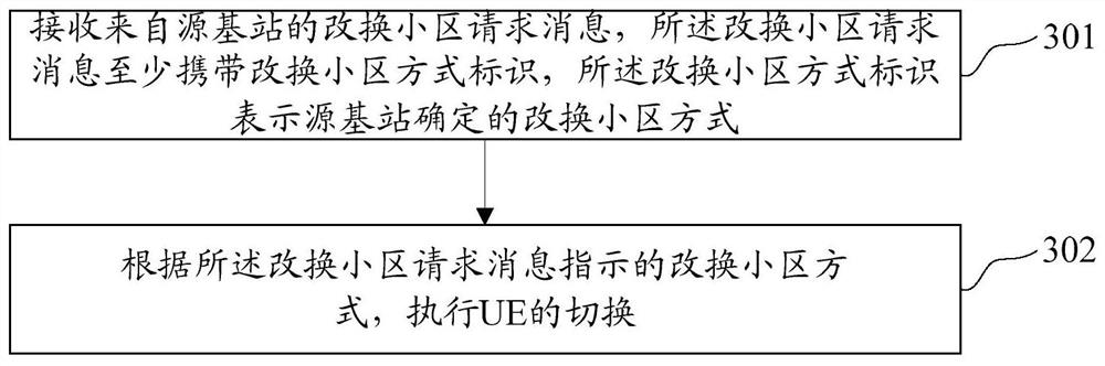
[0225] A mobility management method such as image 3 shown, can include:

[0226] Step 301: Receive a cell change request message from a source base station, where the cell change request message at least carries a cell change mode identifier, and the cell change mode identifier indicates a cell change mode determined by the source base station;

[0227] Step 302, according to the cell change mode indicated by the cell change request message, perform handover of the UE;

[0228] Wherein, the way of changing the cell of the UE includes at least one of the following: maintaining the user plane link of the UE to the source base station; transferring the user plane link of the UE to the target base station.

[0229] In practical applications, the above method in this embodiment may be implemented by the target base station. In practical applications, the target base station may satisfy one of the following: the radio access technology RAT to which it belongs is of the same type ...

Embodiment 3

[0261] A mobility management method such as Figure 5 shown, can include:

[0262] Step 501: Receive a cell change command message issued by the source base station, where the cell change command message is used to instruct the UE to initiate a cell change to the target base station, and the cell change command message at least carries the cell change mode identifier determined by the source base station;

[0263] Step 502, performing handover according to the cell change mode indicated by the cell change command message;

[0264] The UE's cell changing method includes at least one of the following:

[0265] Keep the user plane link of the UE at the source base station;

[0266] The user plane link of the UE is transferred to the target base station.

[0267] In practical applications, the foregoing method in this embodiment may be implemented by the UE. In practical applications, the target base station may satisfy one of the following: the radio access technology RAT to ...


PUM


Abstract

This paper discloses a mobility management method and device, the method includes: after the UE in the inactive state or the light-connected state satisfies the conditions for changing the cell and determines the target base station for the changing cell, determining the changing cell of the user equipment UE performing the handover of the UE according to the determined cell-changing mode; the UE's cell-changing mode includes at least one of the following: keeping the user plane link of the UE at the source base station; transferring the user plane link of the UE to the target base station. The present application implements mobility management between LTE and 5G New RAT in an inactive state or a light connected state.

Description

technical field [0001] The present invention relates to the field of communications, in particular to a mobility management method and device. Background technique [0002] In the long term evolution (Long Term Evaluation, LTE) standard and 5G new radio access network (Radio Access Network, RAN) standard currently discussed by the 3rd Generation Partnership Project (3GPP, the 3rd Generation Partnership Project), LTE is introduced respectively. In the light connected state, the inactive state is introduced in the 5G new RAT. These two states are similar in nature. For LTE RAN and 5G RAN, both the light connected state and the inactive state belong to Radio Resource Control (RRC). , Radio Resource Control) is a sub-state of the connected state. If the terminal is in the light connected state or inactive state, its RRC connection with the RAN is still maintained, and the signaling bearer and data bearer are still maintained, but the difference from the RRC connected state is: t...

Claims


Application Information

Patent Timeline
Patent Type & Authority Patents(China)
IPC IPC(8): H04W36/00H04W36/08
CPCH04W36/0005H04W36/0022H04W36/0033H04W36/0072H04W36/08
Inventor 戴谦
Owner ZTE CORP
Why Eureka
Try Eureka