
A spherical drain water collector for hydraulic mining

A water collector and spherical technology, which is applied in the field of spherical water discharge water collectors, can solve the problems of blockage of spherical water collecting containers, poor water discharge efficiency, small water discharge area, etc., and achieves the effect of reducing blockage and simple structure.

Active Publication Date: 2019-10-29
罗茜
View PDF6 Cites 0 Cited by
  • Summary
  • Abstract
  • Description
  • Claims
  • Application Information

AI Technical Summary

Problems solved by technology

In the process of hydraulic mining, it is necessary to fill in the mined-out area, and the known drainage method of hydraulic filling mining is to build a return pipe to drain water in the mine. The disadvantage is that the drainage area is small, and the drainage efficiency is poor. ; And proposed to set up a plurality of spherical water collection containers connected to the structure of the pipeline, which utilizes the spherical water collection container to open a number of drain holes to increase the drainage efficiency, but also to filter and avoid pipeline blockage However, in the subsequent filling process of the spherical water collection container, if the cemented single paste glue or small filling particles are easy to enter the spherical water collection container through the drain hole, the spherical water collection container will be blocked and the drainage will be affected.

Method used


Image

  • A spherical drain water collector for hydraulic mining
  • A spherical drain water collector for hydraulic mining

Examples


Embodiment

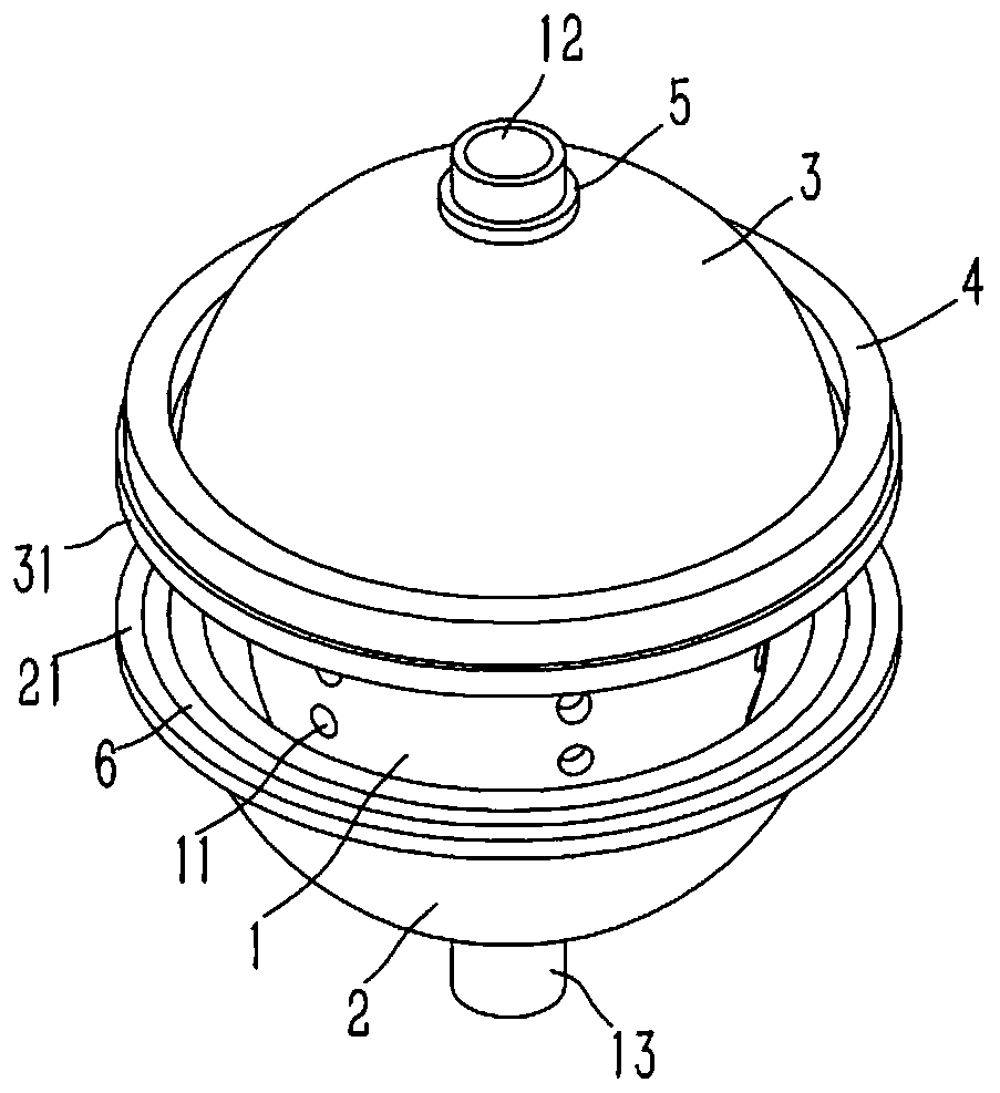
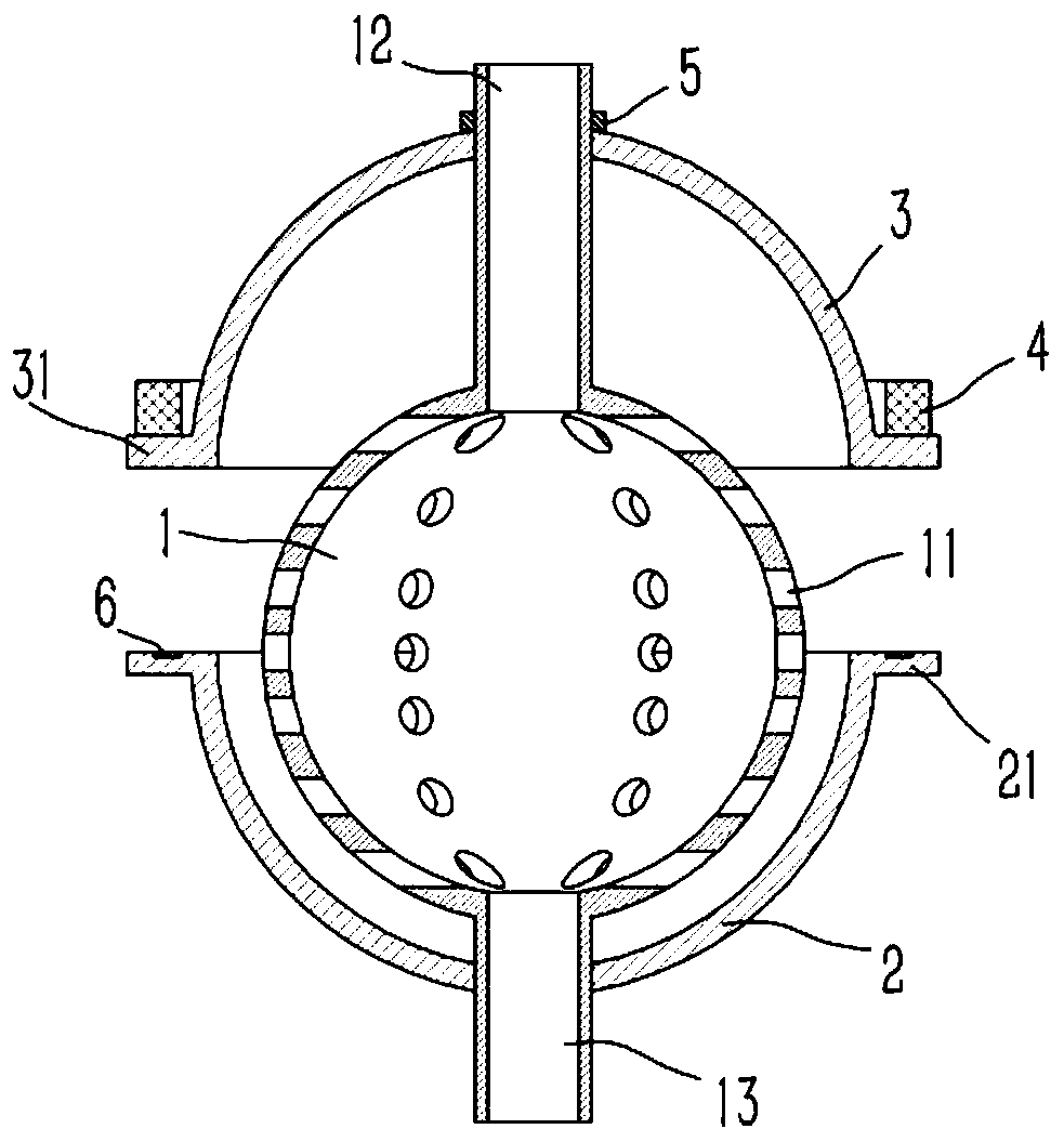
[0015] Example: see figure 1 , 2 As shown, a spherical drainage water collector for hydraulic mining includes a spherical water collector 1, a plurality of drain holes 11 are formed on the water collector 1, and an upper connecting pipe 12 is formed on the top of the water collector 1. , the bottom of the water collector 1 is formed with a lower connecting pipe 13, and the lower connecting pipe 13 is sleeved and fixed with a hemispherical lower casing 2, and the lower casing 2 is inserted and sleeved on the outside of the water collector 1, and the lower casing 2 The upper side is formed with a horizontal annular lower rib 21; the upper connecting pipe 12 is inserted with a hemispherical upper casing 3, the opening of the upper casing 3 faces downward, and the lower side of the upper casing 3 A horizontal annular upper rib 31 is formed, and an annular floating ring 4 is fixed on the upper end surface of the upper rib 31 , and the upper connecting pipe 12 on the upper side of ...


PUM


Abstract

The invention discloses a spherical drain water collector for hydraulic mining. The spherical drain water collector includes a spherical water collector body, a plurality of drainage holes are formedin the water collector body, an upper connecting pipe is formed at the top end of the water collector body, and a lower connecting pipe is formed at the bottom end of the water collector body. A semispherical lower shell is fixed to the lower connecting pipe in an inserting-sleeving mode, the outer side of the water collector body is sleeved with the lower shell in an inserting mode, and a horizontal and annular lower retaining side is formed on the upper side edge of the lower shell. The upper connecting pipe is sleeved with a semispherical upper shell in an inserting mode, an opening of theupper shell faces down, a horizontal and annular upper retaining side is formed on the lower side edge of the upper shell, an annular floating ring is fixed to the upper end face of the upper retaining side, and a limiting ferrule is fixed to the upper connecting pipe and located on the upper side of the upper shell in an inserting-sleeving mode. The spherical drain water collector for hydraulic mining is simple in structure and conducive to the drainage in a mine tunnel, and at the same time, the blockage condition can be reduced.

Description

Technical field: [0001] The invention relates to the technical field of hydraulic filling devices, in particular to a spherical drain water collector for hydraulic mining. Background technique: [0002] Hydraulic mining is a mining method that uses high-pressure jets of water to wash away soil or gravel containing valuable minerals. In the process of hydraulic mining, it is necessary to fill in the mined-out area, and the known drainage method of hydraulic filling mining is to build a return pipe to drain water in the mine. The disadvantage is that the drainage area is small, and the drainage efficiency is poor. ; And proposed to set up a plurality of spherical water collection containers connected to the structure of the pipeline, which utilizes the spherical water collection container to open a number of drain holes to increase the drainage efficiency, but also to filter and avoid pipeline blockage However, in the subsequent filling process of the spherical water collecti...

Claims


Application Information

Patent Timeline
Patent Type & Authority Patents(China)
IPC IPC(8): E21C45/04
CPCE21C45/04
Inventor 徐亚维
Owner 罗茜
Learn More