Eureka AIR delivers breakthrough ideas for toughest innovation challenges, trusted by R&D personnel around the world.

Flue gas treatment and exhausting device based on dynamic seal design

An exhaust device and flue gas treatment technology, which is applied in the directions of combination device, dispersed particle separation, chemical instruments and methods, etc. The effect of gas backflow, prolonging service life and avoiding flue gas backflow

Pending Publication Date: 2018-10-16
雷磊
View PDF0 Cites 1 Cited by
  • Summary
  • Abstract
  • Description
  • Claims
  • Application Information

AI Technical Summary

Problems solved by technology

[0004] During the flue gas treatment, because the device body processes high-temperature flue gas, there will be a temperature difference during the treatment, which will cause a pressure difference in the local area, which will cause the flue gas backflow inside the flue gas treatment equipment. This situation has a great impact on the emission after flue gas treatment, affects its efficiency, and also affects the life of the equipment, so it needs to be improved

Method used


Image

  • Flue gas treatment and exhausting device based on dynamic seal design
  • Flue gas treatment and exhausting device based on dynamic seal design
  • Flue gas treatment and exhausting device based on dynamic seal design

Examples


Embodiment Construction

[0026] The technical solution of this patent will be further described in detail below in conjunction with specific embodiments.

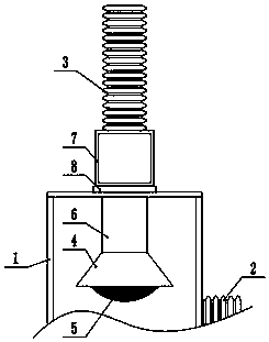
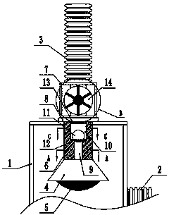
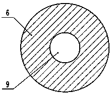
[0027] see Figure 1-6 , a flue gas treatment and exhaust device based on a dynamic sealing design, including a device body, the device body is provided with a treatment chamber 1, and the side of the treatment chamber 1 is provided with a flue gas inlet pipe 2, and the flue gas inlet pipe 2 is connected to the The inside of the processing chamber 1 communicates with each other, the inside of the processing chamber 1 is provided with a smoke guide hood 4, the bottom of the described smoke guide 4 is provided with a filter screen 5, and the effect of the screw between the filter screen 5 and the smoke guide 4 Fixedly connected, the top of the smoke hood 4 is provided with an anti-backflow mechanism 6, the anti-backflow mechanism 6 is welded to the smoke hood 4, the anti-backflow mechanism 6 is connected to the top of the processing chamber 1, and th...


PUM


Abstract

The invention discloses a flue gas treatment and exhausting device based on dynamic seal design. The device comprises a device body, wherein the device body is provided with a treatment chamber; a flue gas inlet pipe is arranged on the side surface of the treatment chamber; a flue gas guide hood is arranged in the treatment chamber; a backflow preventing mechanism is arranged at the top of the flue gas guide hood; an exhausting assistant mechanism is arranged at the top of the treatment chamber; a flue gas exhausting pipe is arranged at the top of the exhausting assistant mechanism; a first ventilation pipeline and a second ventilation pipeline are arranged in the backflow preventing mechanism. Under the action of the dynamic sealing structure, the effective sealing effect can be guaranteed under different pressure differences, flue gas backflow is avoided, flue gas emission can be effectively assisted by the exhausting assistant mechanism, and by means of unidirectional rotation, flowgas backflow is effectively reduced; therefore, the device is novel in overall design and simple in structure, the flow gas backflow is avoided effectively, the flue gas treatment effect is improved,flue gas treatment equipment is protected, and the service life is prolonged.

Description

technical field [0001] The invention relates to a dynamic sealing structure, in particular to a flue gas treatment and exhaust device based on a dynamic sealing design. Background technique [0002] The flue gas treatment equipment is to effectively treat the toxic and harmful substances contained in the flue gas to below the specified concentration, and avoid corrosion or blockage of the equipment. Generally, the flue gas treatment equipment used in waste incineration plants is divided into two categories: dust removal equipment and acid gas removal equipment. Now, with the improvement of people's requirements for environmental quality, most waste incineration plants have added activated carbon adsorption heavy metal equipment in the flue gas treatment process. [0003] Flue gas treatment equipment mainly includes flue gas desulfurization tower, flue gas scrubber, absorption tower, absorption medium transmission pipe network, chimney and flue, etc., which are mainly used i...

Claims


Application Information

Patent Timeline
IPC IPC(8): B01D45/14B01D50/00
CPCB01D45/14B01D50/20
Inventor 雷磊
Owner 雷磊
Why Eureka
Eureka Blog
Learn More