

Polishing pad and grinding device
A polishing pad and grinding surface technology, applied in the field of polishing pads
Pending Publication Date: 2018-10-16
HUBEI DINGLONG CO LTD +1
View PDF0 Cites 10 Cited by
- Summary
- Abstract
- Description
- Claims
- Application Information
AI Technical Summary
Problems solved by technology
However, the polishing pads of the above four existing stru
Method used
View moreImage
Smart ImageViewing Examples

Examples
 PUM
 Abstract
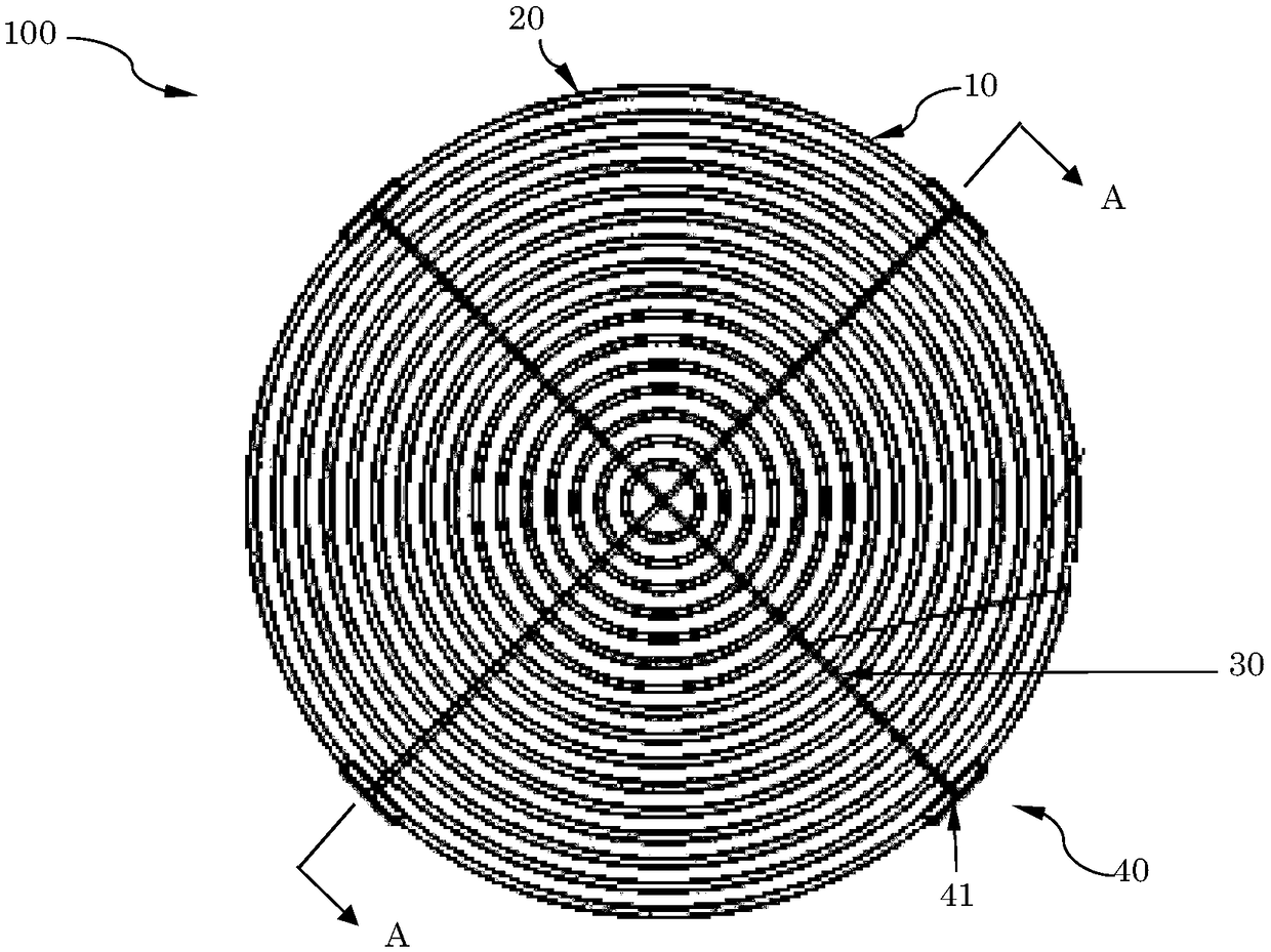
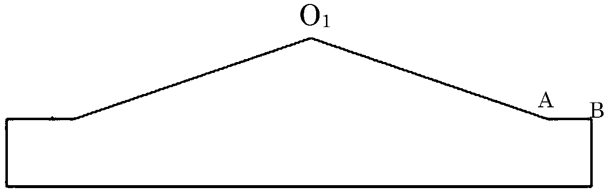
The invention discloses a polishing pad. The polishing pad comprises a pad body with the grinding surface, at least two ring grooves which are sleeved with each other and formed on the grinding surface, and at least one linear groove which is formed in the grinding surface and penetrates through each ring groove to communicate with the penetrated ring groove, wherein the depth of the linear groovechanges and increases along with increasing of the distance of being away from the center of the innermost ring groove. On the one hand, the mutually-sleeved ring grooves are formed in the grinding surface of the pad body so that polishing liquid entering the polishing pad can be blocked and kept for an appropriate staying time, and the polishing effect is achieved. On the other hand, the lineargroove penetrating through each ring groove to communicate with penetrated ring groove can guide the polishing liquid finishing the polishing process out of the ring grooves, and particularly, as thedepth of the linear groove increases along with increasing of the distance of being away from the center of the innermost ring groove, under the action of the inclined surface, the polishing liquid can be naturally discharged by means of the gravity,
Description
technical field [0001] The invention relates to a polishing pad, which belongs to the field of chemical / mechanical polishing. Background technique [0002] Chemical-mechanical planar polishing or chemical-mechanical polishing (CMP) is currently the most commonly used technique for surface polishing of workpieces. CMP is a composite technology obtained by combining chemical erosion and mechanical removal, and it is also the most commonly used technology for planarization of semiconductor wafers. [0003] At present, in the conventional CMP process, the wafer is installed on the support assembly of the grinding equipment, and the position where the wafer contacts the polishing pad during the polishing process is set by adjusting related parameters. During the polishing process, the wafer is pressed against the polishing pad with controlled pressure, and the polishing pad is rotated relative to the wafer by external driving force. During the relative rotation process, the pol...
Claims
Login to View More Application Information
Patent Timeline
 IPC IPC(8): B24B37/26
CPCB24B37/26
Inventor朱顺全吴晓茜张季平车丽媛
OwnerHUBEI DINGLONG CO LTD