
Microwave antenna control system

A microwave antenna and control system technology, applied in directions such as antennas, antenna parts, measuring devices, etc., can solve the problems of difficult operation, direction error, complicated adjustment process, etc., and achieve the effect of easy operation and simple structure.

Pending Publication Date: 2018-10-16
PROSE TECH CO LTD
View PDF7 Cites 3 Cited by
  • Summary
  • Abstract
  • Description
  • Claims
  • Application Information

AI Technical Summary

Problems solved by technology

In addition, in order to increase the communication distance, the microwave antenna is often erected high, so the alignment direction of the microwave antenna is easily affected by the weather and cause direction errors. Therefore, adjusting the direction of the antenna is one of the main problems currently facing
[0003] In the existing technology, the adjustment of the antenna angle needs to climb to a high place for on-site adjustment, and at the same time, it is necessary to wear the necessary equipment such as wrench and direction indicator. The adjustment process is complicated, the operation is difficult, and it is difficult to achieve the precise adjustment target.

Method used


Image

  • Microwave antenna control system
  • Microwave antenna control system
  • Microwave antenna control system

Examples


Embodiment Construction

[0025] The technical solutions of the embodiments of the present invention will be clearly and completely described below in conjunction with the accompanying drawings of the present invention.

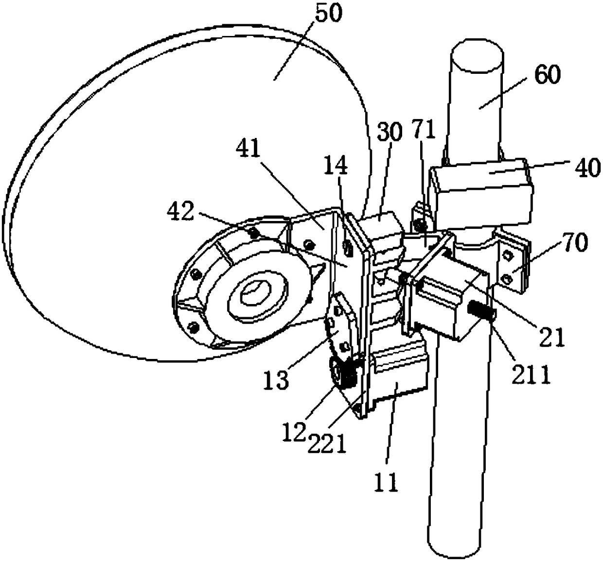
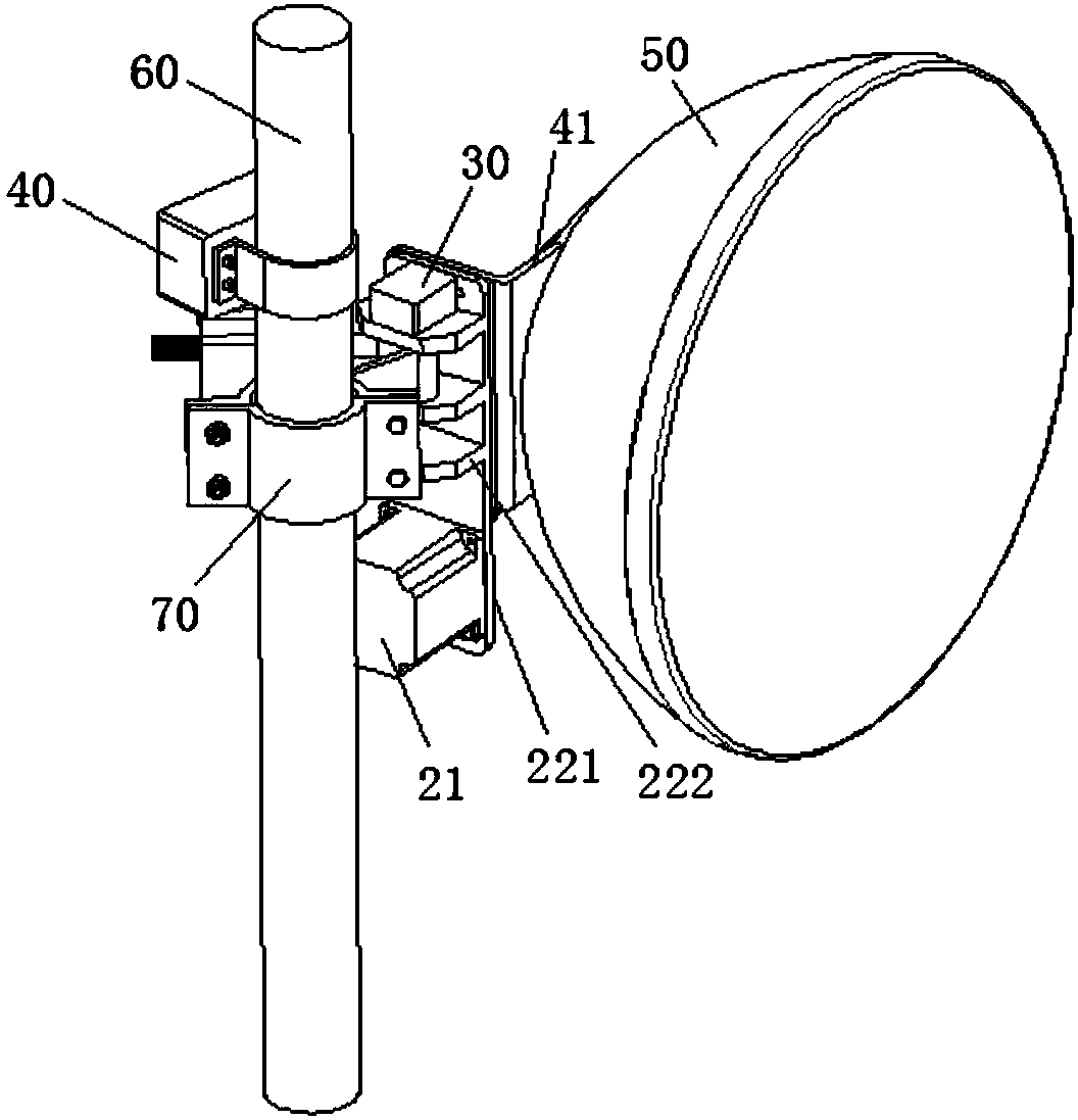
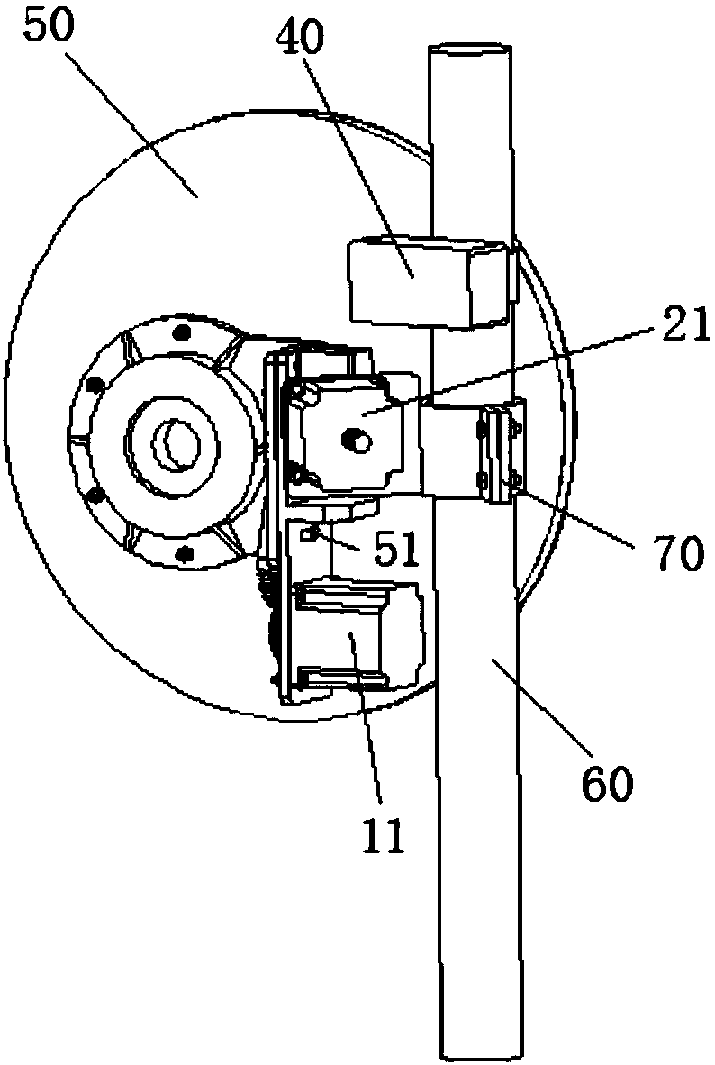
[0026] combine Figure 1 ~ Figure 4 As shown, a microwave antenna control system disclosed in the embodiment of the present invention includes a first driving device, a second driving device, an angle sensor 30, and a control unit 40, wherein the first driving device, the second driving device, the angle sensor 30 is connected to the microwave antenna 50, and the three are also connected to the control unit 40. The angle sensor 30 is used to monitor the angle information of the microwave antenna 50, and the control unit 40 controls the first driving device and / or the second drive device according to the angle information. The driving device automatically adjusts the angle of the microwave antenna 50 .

[0027] Wherein, the microwave antenna 50 is connected with the first driving devi...


PUM


Abstract

The invention discloses a microwave antenna control system, and the system is used for automatically adjusting the angle of a microwave antenna. The system comprises a first driving device, a second driving device, an angle sensor and a control unit, wherein the first driving device, the second driving device and the angle sensor are connected with the microwave antenna and are also connected withthe control unit. The angle sensor monitors the angle information of the microwave antenna, and the control unit controls the first driving device and / or the second driving device to accurately and automatically adjust the angle of the microwave antenna according to the angle information. The system is simple in structure and is easy to operate.

Description

technical field [0001] The invention relates to an antenna angle adjusting device, in particular to a control system for automatically controlling and adjusting the angle of a microwave antenna. Background technique [0002] Microwave antennas, also known as reflector antennas, are mainly used for receiving and transmitting microwave signals. In order to improve the propagation quality of microwave signals generated between the antennas, it is necessary to adjust the microwave antennas to ensure that the two main lobes of the two microwaves are in space Overlap or overlap as much as possible. In addition, in order to increase the communication distance, the microwave antenna is often erected high, so the alignment direction of the microwave antenna is easily affected by the weather and cause direction errors. Therefore, adjusting the direction of the antenna is one of the main problems currently faced. [0003] In the existing technology, the adjustment of the antenna angle...

Claims


Application Information

Patent Timeline
Patent Type & Authority Applications(China)
IPC IPC(8): H01Q3/08
CPCH01Q3/08H01Q1/125H01Q1/1228G01C9/12G01C2009/062H01Q15/14
Inventor 彭道兵J·萨伊德
Owner PROSE TECH CO LTD
Learn More