Welding clamp for annular pieces and cylindrical pieces

A technology for welding fixtures and ring parts, applied in welding equipment, auxiliary welding equipment, welding/cutting auxiliary equipment, etc., can solve the problems of manual station change, station switching, and station inability to achieve mechanical fixation, Achieve transformation and ensure efficiency

Inactive Publication Date: 2018-10-19
苏州瑞沁精密机械有限公司
View PDF6 Cites 0 Cited by
  • Summary
  • Abstract
  • Description
  • Claims
  • Application Information

AI Technical Summary

Problems solved by technology

[0002] In the process of tooling, welding between small parts is often encountered. If the number of parts is small and the number of parts is large, if the parts are manually welded one by one, it will take a long time and is extremely inconvenient. However, the existing fixtures are mostly used for single welding. , and once it is fixed by the fixture, the station is fixed and cannot be switched between stations. At this time, it is necessary to manually change the station

Method used


Image

  • Welding clamp for annular pieces and cylindrical pieces
  • Welding clamp for annular pieces and cylindrical pieces

Examples


Embodiment Construction

[0014] The present invention will be further explained in detail below in conjunction with the accompanying drawings and specific embodiments, but it should be understood that the protection scope of the present invention is not limited by the specific embodiments.

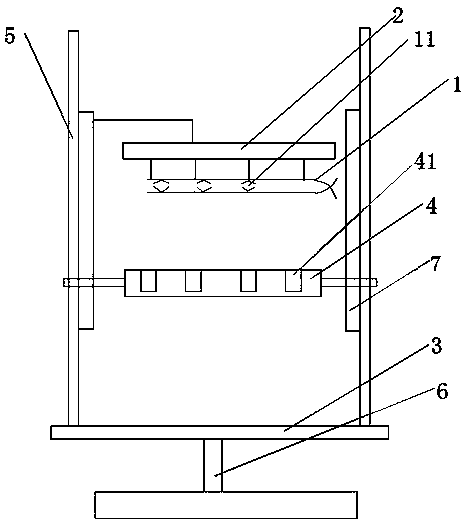
[0015] A welding jig for a ring and a column, comprising a first jig 1 capable of clamping a plurality of columns and a second jig 4 for clamping a plurality of rings, and also including fixing the first jig 1 and the second jig 4 The support includes a vertically arranged pole 5 and a horizontally arranged chassis 3, the pole 5 is provided with a slide rail 7, the first clamp 1 and the second clamp 4 are arranged up and down oppositely, the described The first clamp 1 can approach or move away from the second clamp 4 along the slide rail 7, the first clamp 1 includes a clip with a plurality of clamping holes 11, and the clip includes two symmetrically arranged bodies, The two pieces are provided with arc-shaped d...


PUM


Abstract

The invention relates to a welding clamp for annular pieces and cylindrical pieces. The welding clamp comprises a first clamp body capable of clamping the multiple cylindrical pieces and a second clamp body clamping the multiple annular pieces, and further comprises a bracket for fixing the first clamp body and the second clamp body; the bracket comprises a vertically-arranged supporting rod and ahorizontally-arranged bottom disc; the supporting rod is provided with a sliding rail; the first clamp body and the second clamp body are arranged in an up-down opposite mode, the first clamp body can get close to or get away from the second clamp body along the sliding rail, the first clamp body comprises a clamp main body provided with a plurality of clamping holes, and the clamp main body comprises two-sheet bodies which are arranged symmetrically, arc-shaped dimples are arranged on the two-sheet bodies correspondingly, and the arc-shaped dimples on the two-sheet bodies form the clamping holes in a one-to-one correspondence mode; and the second clamp body is an annular dimple formed in a face plate, and the annular pieces are placed in the annular dimple. The multiple workpieces can bewelded simultaneously by the clamp, and are prevented from being staggered through clamp positioning.

Description

technical field [0001] The invention relates to a fixture, in particular to a welding fixture, which is used for welding a ring piece and a column piece. Background technique [0002] In the process of tooling, welding between small parts is often encountered. If the number of parts is small and the number of parts is large, if the parts are manually welded one by one, it will take a long time and is extremely inconvenient. However, most of the existing fixtures can be used for single welding. , and once fixed by the fixture, the station is fixed and cannot be switched between stations. At this time, it is necessary to manually change the station. Contents of the invention [0003] The object of the present invention is to provide a welding jig between the ring part and the column part of a small part, which can weld multiple parts at the same time, and can be positioned by the jig to prevent misalignment. [0004] The technical solution adopted by the present invention i...

Claims


Application Information

Patent Timeline
IPC IPC(8): B23K37/047
CPCB23K37/047
Inventor 姚水华
Owner 苏州瑞沁精密机械有限公司
Why Eureka
Try Eureka