Fit clearance continuously-adjustable thrust rolling bearing test bench
A rolling bearing and fit clearance technology, which is applied in the direction of mechanical bearing testing, etc., can solve the problems such as the inability to meet the continuous changing characteristics of the fit clearance, and achieve the effects of avoiding uneven load, continuously adjustable fit clearance, and easy operation.
- Summary
- Abstract
- Description
- Claims
- Application Information
AI Technical Summary
Problems solved by technology
Method used
Image
Examples
specific Embodiment approach 1
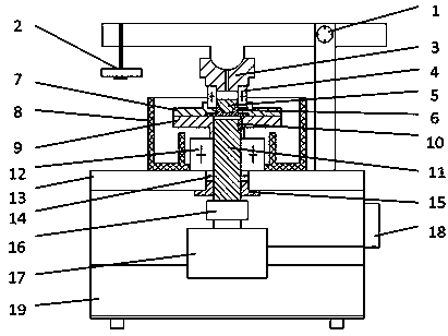
[0011] Specific implementation mode one: combine figure 1 , a detailed fit gap continuously adjustable thrust rolling bearing test bench is characterized in that it includes a support plate 13 on which a lever loading device 1 is mounted, and the lever loading device includes a lever base, a lever bracket baffle, a lever bracket, and a rolling bearing, Lever shaft, lever bearing gasket, lever bearing end cover, a weight 2 is placed at one end of the lever, the loading contact part is a cylindrical contact block, 1 / 3 away from the fulcrum, the load is transmitted to the bearing cover 3 through the cylindrical contact block, The upper cover of the bearing is matched with the shaft ring of the thrust rolling bearing 4 to be tested, the seat ring of the thrust rolling bearing 4 to be tested is placed in the bearing housing 7, the semi-conical hollow shaft 6 is matched with the inner ring of the thrust rolling bearing 4 to be tested, and the The shape pin 5 adjusts the fit clearanc...
specific Embodiment approach 2
[0012] Specific implementation mode two: combination figure 1 , in detail, the working principle of the thrust rolling bearing test bench with continuously adjustable fit gap is as follows: After adding weight 2, a load three times the weight is applied to the bearing cover 3 through the principle of leverage, thereby applying a load to the thrust rolling bearing 4 to be tested. The external controller 18 triggers the driving machine 17 to work. The main shaft 11 is driven to rotate by the elastic coupling 16 . The bearing seat tray 9 and the bearing seat 7 are connected by countersunk screws, and the main shaft 11 drives the bearing seat tray 9 and the bearing seat 7 to rotate together through the flat key 10 after the rotation. Under the double cooperation of the seat ring of the thrust rolling bearing 4 to be tested, the bearing seat 7 and the semi-conical hollow shaft 6, the seat ring of the thrust rolling bearing 4 to be tested rotates. The oil dripped into the central ...
specific Embodiment approach 3
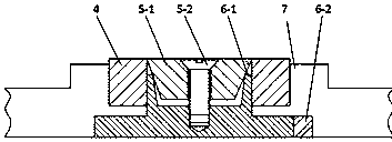
[0013] Specific implementation mode three: combination figure 2 , detailing the working principle of the double fit between the thrust rolling bearing seat ring and the semi-conical hollow shaft and the bearing seat of the thrust rolling bearing test bench with continuously adjustable fit clearance: the outer ring of the thrust rolling bearing 4 seat ring to be tested and the bearing seat 7 adopt a clearance fit. A semi-conical hollow shaft 6-1 with a taper of 17° is embedded in the bottom of the bearing seat 7 to form a matching pair with the inner ring of the thrust rolling bearing race 4 to be tested. And in the axial direction of the semi-conical hollow shaft 6-1, two U-shaped slots with a width of 1 mm are symmetrically opened to the conical hollow tail end. Semi-tapered hollow shaft 6-1 and bearing seat 7 realize synchronous rotation by flat key 6-2. Taper is that the conical pin 5-1 of 30 ° is pressed in the semi-conical hollow shaft 6-1 by countersunk head screw 5-2....
PUM
 Abstract
Description
Claims
Application Information
 - R&D
- Intellectual Property
- Life Sciences
- Materials
- Tech Scout
- Unparalleled Data Quality
- Higher Quality Content
- 60% Fewer Hallucinations
Browse by: Latest US Patents, China's latest patents, Technical Efficacy Thesaurus, Application Domain, Technology Topic, Popular Technical Reports.
© 2025 PatSnap. All rights reserved.Legal|Privacy policy|Modern Slavery Act Transparency Statement|Sitemap|About US| Contact US: help@patsnap.com


