
Tool wear state monitoring method and equipment

A wear state and tool wear technology, applied in the computer field, can solve problems such as increased factory energy consumption, influence of milling process quality, instability, etc., to avoid equipment downtime and comprehensive utilization rate, increase equipment utilization rate, and reduce energy consumption. cost effect

Active Publication Date: 2021-08-10
上海实极机器人自动化有限公司
View PDF0 Cites 0 Cited by
  • Summary
  • Abstract
  • Description
  • Claims
  • Application Information

AI Technical Summary

Problems solved by technology

[0002] In the fully automatic production process of industrial robots, the number of times the milling cutter is used is currently set through long-term production experience. After the number of times is exceeded, the measure of forced tool change is carried out. Although this can initially solve the problem of tool wear on the quality of milling, but Such measures are unstable and uncontrollable, because when the wear degree of the tool is lower than the blunt standard, changing the tool will inevitably greatly increase the energy consumption of the factory, and if the tool is greater than the blunt standard, although the tool is extended service life, but it is bound to have a great impact on the quality of milling process

Method used


Image

  • Tool wear state monitoring method and equipment
  • Tool wear state monitoring method and equipment
  • Tool wear state monitoring method and equipment

Examples


Embodiment Construction

[0048] The present invention will be described in further detail below in conjunction with the accompanying drawings.

[0049] In a typical configuration of the present application, the terminal, the device serving the network and the trusted party all include one or more processors (CPUs), input / output interfaces, network interfaces and memory.

[0050] Memory may include non-permanent storage in computer readable media, in the form of random access memory (RAM) and / or nonvolatile memory such as read only memory (ROM) or flash RAM. Memory is an example of computer readable media.

[0051] Computer-readable media, including both permanent and non-permanent, removable and non-removable media, can be implemented by any method or technology for storage of information. Information may be computer readable instructions, data structures, modules of a program, or other data. Examples of computer storage media include, but are not limited to, phase change memory (PRAM), static rando...


PUM


Abstract

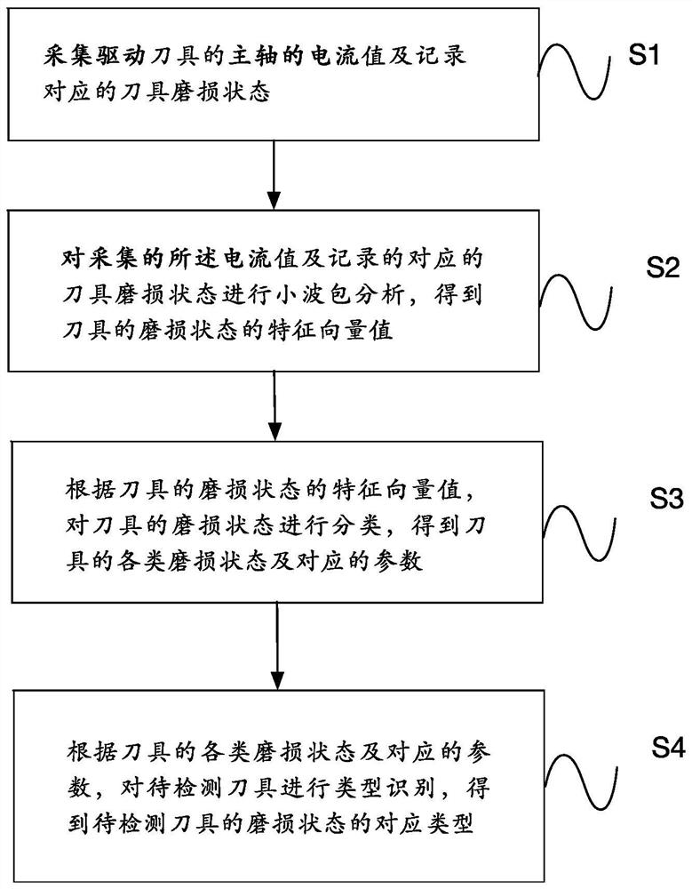
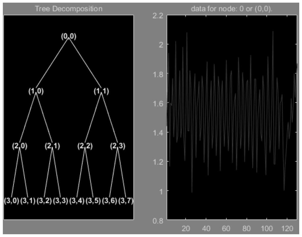
The purpose of the present invention is to provide a tool wear state monitoring method and equipment. The present invention summarizes the signal acquisition type of the most effective spindle current signal for actual production conditions from the aspects of cost and implementation, and then conducts a process on the collected spindle current signal The wavelet packet analysis and processing obtains the signals of the high-frequency part, and the signals of these high-frequency components can well reflect the wear state of the tool. Finally, the wear state is judged through the Softmax regression algorithm or the BP neural network, forming a set of reasonable and effective solutions. solution, the present invention greatly reduces the occurrence of human factors, thus avoiding the equipment shutdown rate and comprehensive utilization rate caused by workers' frequent tool changes, thereby greatly increasing the equipment utilization rate and further reducing the energy consumption of the factory cost.

Description

technical field [0001] The invention relates to the field of computers, in particular to a method and equipment for monitoring tool wear status. Background technique [0002] In the fully automatic production process of industrial robots, the number of times the milling cutter is used is currently set through long-term production experience. After the number of times is exceeded, the measure of forced tool change is carried out. Although this can initially solve the problem of tool wear on the quality of milling, but Such measures are unstable and uncontrollable, because when the wear degree of the tool is lower than the blunt standard, changing the tool will inevitably greatly increase the energy consumption of the factory, and if the tool is greater than the blunt standard, although the tool is extended service life, but it is bound to have a great impact on the quality of milling process. Contents of the invention [0003] One object of the present invention is to prov...

Claims


Application Information

Patent Timeline
Patent Type & Authority Patents(China)
IPC IPC(8): B23Q17/09
CPCB23Q17/0995
Inventor 许顺强蔡晟
Owner 上海实极机器人自动化有限公司
Learn More