LED Lighting Fixture with Reconfigurable Light Distribution Pattern

a technology of led lighting fixtures and light distribution patterns, applied in lighting and heating apparatus, lighting support devices, light source combinations, etc., can solve the problems of wasteful light distribution of lighting systems traditionally used in wide area applications such as storage warehouses or manufacturing floors, limiting standard methods of general illumination of wide areas, and increasing capital, maintenance and energy consumption. cost, weight and energy consumption, easy re-hung or re-arranged

Active Publication Date: 2012-10-04
INNOVATIVE LIGHTING LLC
View PDF9 Cites 87 Cited by
  • Summary
  • Abstract
  • Description
  • Claims
  • Application Information

AI Technical Summary

Benefits of technology

[0008]To meet these needs, the present invention provides a lighting fixture that utilizes high intensity light emitting diodes (LEDs) for efficiency of weight, size and energy consumption and that can be easily re-hung or rearranged to meet the changing needs of a warehouse or manufacturing area lay-out. Each individual LED light source includes one of several lenses to direct the light in a particular direction resulting in a lighting pattern. The use of different lenses will create a specific and precise illumination area or footprint that can be designed particular to the lighting needs that exist below the placement of the fixture. The fixture itself is easily reconfigurable to produce different light output patterns to conform to the changing environment. When the warehouse or manufacturing floor is so illuminated, the amount of waste light falling on unwanted areas will be reduced resulting in a surgically efficient use of light conforming to the topographic irregularities of the illuminated area and therefore resulting in a lowered cost in energy, a lower number of fixtures and less maintenance, while maintaining satisfactory lighting where the light it is required for efficient operation.

Problems solved by technology

Lighting systems traditionally used in wide area applications such as storage warehouses or manufacturing floors are wasteful in their distribution of light because much of their illumination falls on the tops of pallet racks, palletized goods or manufacturing equipment.
These standard methods of general illumination of wide areas are limiting as their light output is wasteful by not being very well controlled and therefore the conventional remedy for inadequate lighting in areas covered by this sort of blanket lighting solution is to add additional light fixtures and therefore increase cost in capital, maintenance and energy usage.
High intensity discharge lamps have many drawbacks in a warehouse and manufacturing area application.
Even if such considerations are made initially, the lighting scheme becomes impractical once the warehouse or manufacturing floor layout is changed.
Changing the location of high intensity discharge lamps is difficult as the fixtures are heavy and require the replacement of metal conduit for their high voltage AC power supplies, and the lamps require connection to a suitable roof truss or robust support element due to the weight of the fixtures.
Due to the nature of high intensity discharge lamps it is extremely difficult to direct the light output in a manner precise enough for the purposes of creating defined illumination areas for warehouse or manufacturing operations.
The complexity of the optics, heat issues and the uncontrollability of vast quantities of light makes the concept of customizable light pattern outputs unrealistic.
Due to the necessity of forklifts and other equipment in such areas, florescent light fixtures still have to be located above the uppermost levels of most storage racks or manufacturing equipment and due to the wide radiant light output pattern of florescent lights a substantial amount of the light is left illuminating the tops of storage racks or the upper surfaces of manufacturing equipment which results in a great deal of wasted or misspent light.

Method used


Image

  • LED Lighting Fixture with Reconfigurable Light Distribution Pattern
  • LED Lighting Fixture with Reconfigurable Light Distribution Pattern
  • LED Lighting Fixture with Reconfigurable Light Distribution Pattern

Examples


Embodiment Construction

[0029]In the following detailed description, reference is made to the accompanying drawings which form a part hereof, and in which is shown by way of illustration specific embodiments in which the invention may be practiced. These embodiments are described in detail sufficient to enable those skilled in the art to practice the invention, and it is to be understood that other embodiments may be utilized and that structural, logical and mechanical changes may be made without departing from the spirit and scope of the present invention. The following detailed description is, therefore, not to be taken in a limiting sense, and the scope of the present invention is defined by the appended claims.

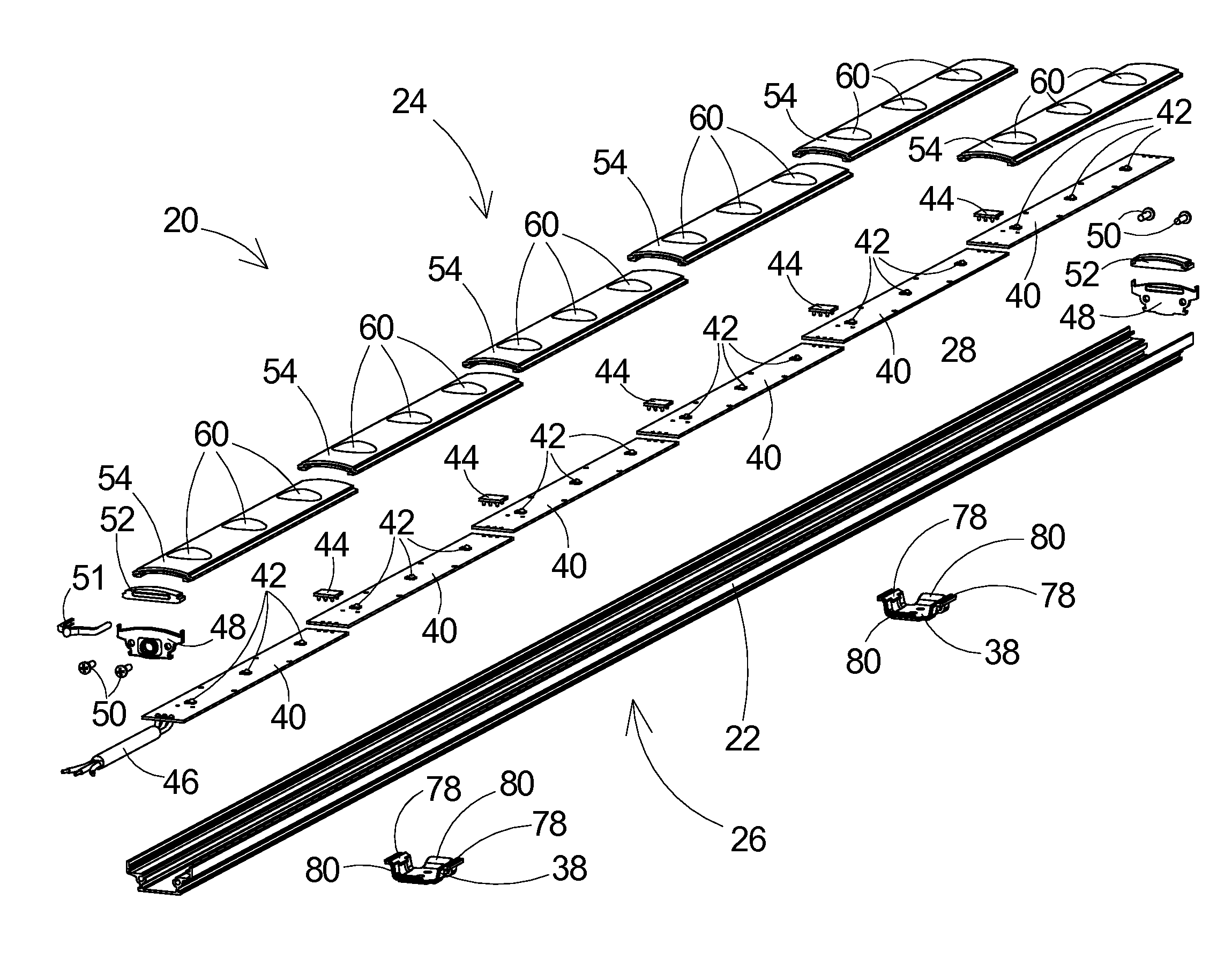
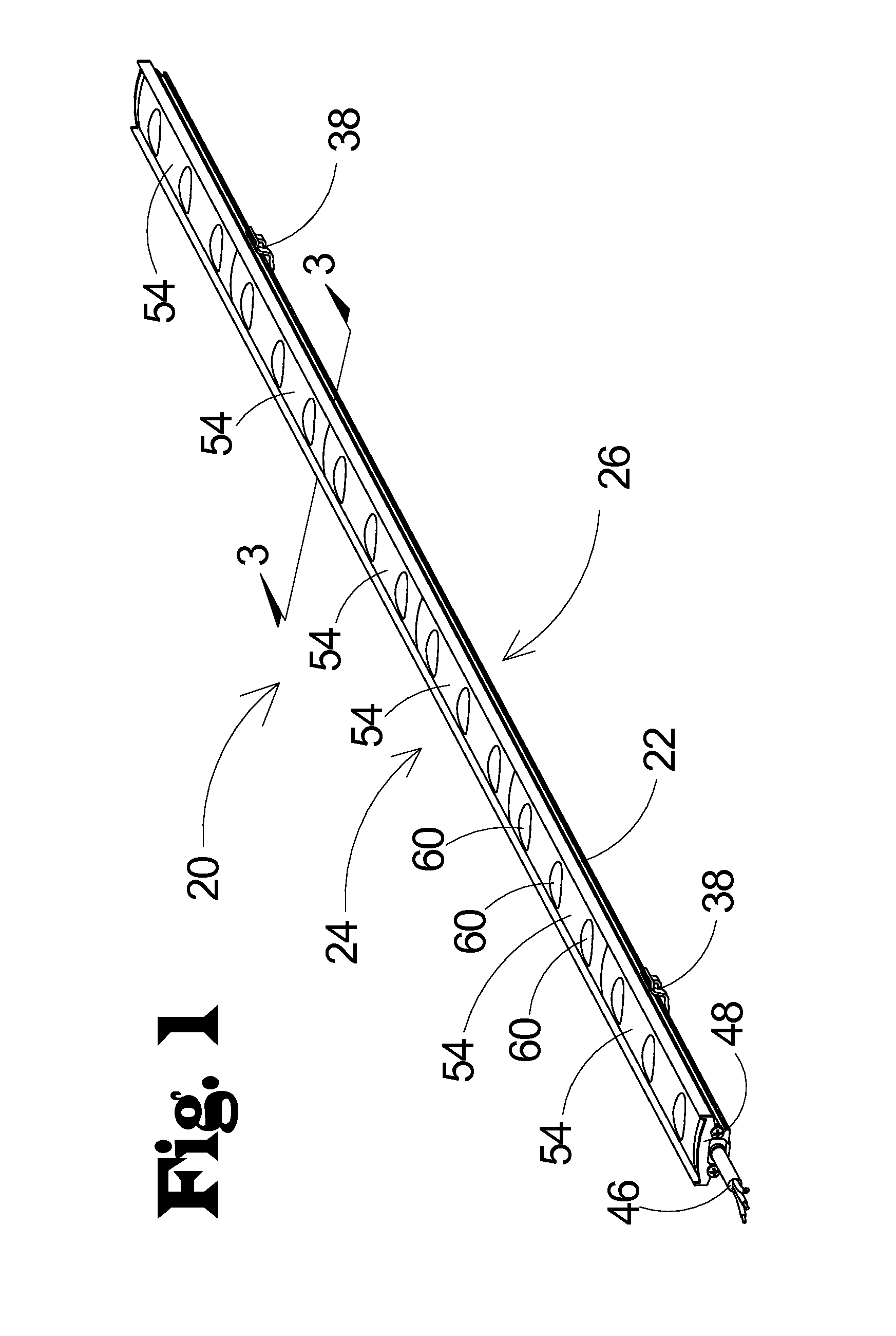
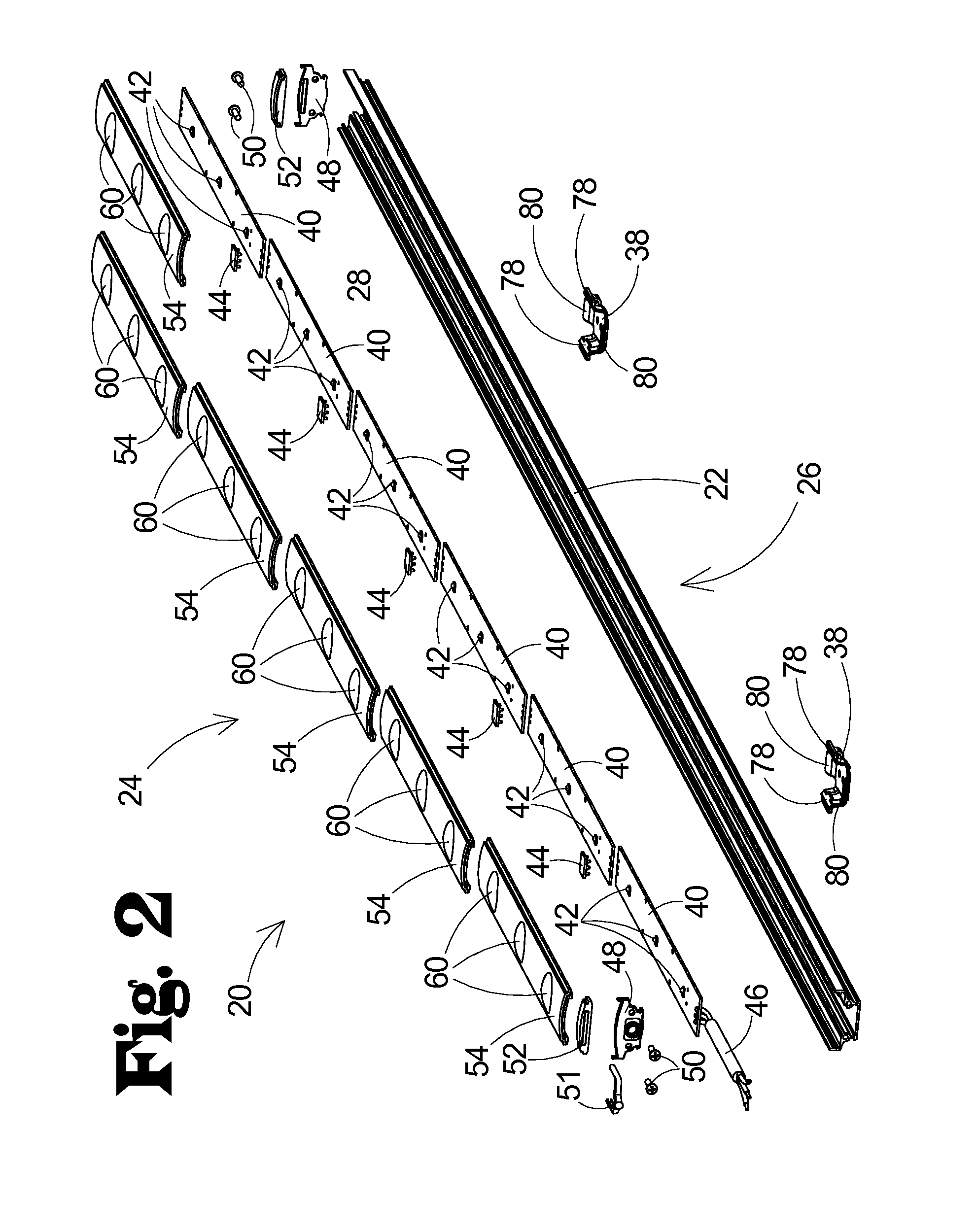
[0030]Illustrated in FIGS. 1-3 is an embodiment of an LED light fixture (20). The fixture base (22) consists of an elongated stanchion with a generally crescent shaped cross section. The semi-enclosed side of the fixture base (22) is referred to as the bezel side (24) which is opposite from the b...


PUM


Abstract

A lighting fixture utilizing light emitting diodes and easily reconfigurable lenses to provide customizable lighting patterns to more efficiently illuminate work or storage areas.

Description

FIELD OF THE INVENTION[0001]The present invention relates to a wide area LED lighting fixture as would be used in a storage warehouse, manufacturing floor or the like.BACKGROUND OF THE INVENTION[0002]Lighting systems traditionally used in wide area applications such as storage warehouses or manufacturing floors are wasteful in their distribution of light because much of their illumination falls on the tops of pallet racks, palletized goods or manufacturing equipment. Common lighting systems of this type include a variety of high intensity discharge lamps such as metal halide, mercury vapor, lead-gallium, high pressure sodium, etcetera. Another common solution for lighting such an area is florescent lamps. These standard methods of general illumination of wide areas are limiting as their light output is wasteful by not being very well controlled and therefore the conventional remedy for inadequate lighting in areas covered by this sort of blanket lighting solution is to add additiona...

Claims


Application Information

Patent Timeline
Patent Type & Authority Applications(United States)
IPC IPC(8): F21V5/04
CPCF21V5/007F21V5/04F21V15/015F21V17/002F21V17/104F21V21/025F21V27/02F21Y2113/00F21S4/28F21Y2103/10F21Y2115/10
Inventor HANDSAKER, JERRY
Owner INNOVATIVE LIGHTING LLC
Why Eureka
Try Eureka