Configurable arrays for steerable antennas and wireless network incorporating the steerable antennas

a technology of steerable antennas and antenna arrays, applied in the field of antennas, can solve the problems of increasing the size of the antenna array, increasing the cost of antenna installation, and increasing the cost of antenna installation, and achieve the effect of more selective control

Inactive Publication Date: 2005-03-22
ANDERSON THEODORE R
View PDF13 Cites 54 Cited by
  • Summary
  • Abstract
  • Description
  • Claims
  • Application Information

AI Technical Summary

Benefits of technology

Yet another object of the invention is to provide a wireless networking system with increased data transfer capacity between users.
An alternate embodiment of the shield utilizes a cylindrical array of switchable variable conductive elements to provide more selective control over where openings in the shield are formed. The cylindrical shield with the array surrounds an antenna. The elements forming the array are arranged in multiple rows and columns on a substrate. The substrate can be a planar sheet rolled into a cylinder shape. The variable conductive elements can be either switchable regions surrounding fixed air gaps or slots, so that the effective size of the fixed slots can be changed rapidly, or the elements can be formed as linear conductors, rectangles, stars, crosses or other geometric shapes of plasma tubes, photonic bandgap crystals or solid state semiconductors on the substrate.
A more complex shield for the antenna has one or more stacked layers, with each layer being a cylindrical switchable array of shield elements. The layers are spaced within one wavelength of adjacent layers to ensure proper function. Each switchable array in the stack can be a filter, a polarizer or a phase shifter. The layers are combined to produce a particular effect, such as producing a steerable antenna transmitting only polarized signals in specific frequency bands.

Problems solved by technology

Antenna arrays normally have a significant footprint, which increases greatly as the angular width of the transmission lobe is reduced.
Due to this, metal antennas are somewhat limited in breadth as to the frequency bands that they may radiate or receive.
Current wireless communications are limited to particular ranges of the electromagnetic frequency spectrum.
High-speed communications are limited by the selected frequency spectrum and number of users which must be accommodated.
Also, because most non-line-of-sight wireless communications are now done using omnidirectional antennas, transmissions between wireless communicators may be easily intercepted by an unintended recipient having the correct equipment.
Transmissions require data encryption to provide some security, which detracts from computing speed and can increase the amount of data transmitted.
In the case of wireless home networking, for example, it is simple for an unauthorized user to connect via a compatible wireless device due to the omnidirectional nature of the antennas used to transmit and receive the network communications between devices.
This inability to limit access by the shape of the area within the wireless network inherent in known wireless networks is one reason for slow acceptance of wireless networks in offices and other work environments where communications security is needed.
Further, because omnidirectional antennas broadcast indiscriminately, an unauthorized user can find an available wireless network to piggy-back on, or worse, break into, using basic signal detection equipment.
Larger arrays with more antennas necessarily require more space to work effectively, and therefore have a larger footprint than a single omnidirectional antenna or a small array.
Thus, conventional antenna arrays are not practical for home and office wireless communications applications due to their large size requirements for effectively directing the radiation lobes of the broadcasting antenna.
But, even military applications are limited by the size requirements for direction antenna arrays.
While it is relatively simply to install an array on an aircraft carrier, it is essentially impossible to install an effective array on a Humvee or fighter jet, for example.
Metal antennas experience a delay during switching, so that changing the transmission lobe direction in an array is not instantaneous.

Method used


Image

  • Configurable arrays for steerable antennas and wireless network incorporating the steerable antennas
  • Configurable arrays for steerable antennas and wireless network incorporating the steerable antennas
  • Configurable arrays for steerable antennas and wireless network incorporating the steerable antennas

Examples


Embodiment Construction

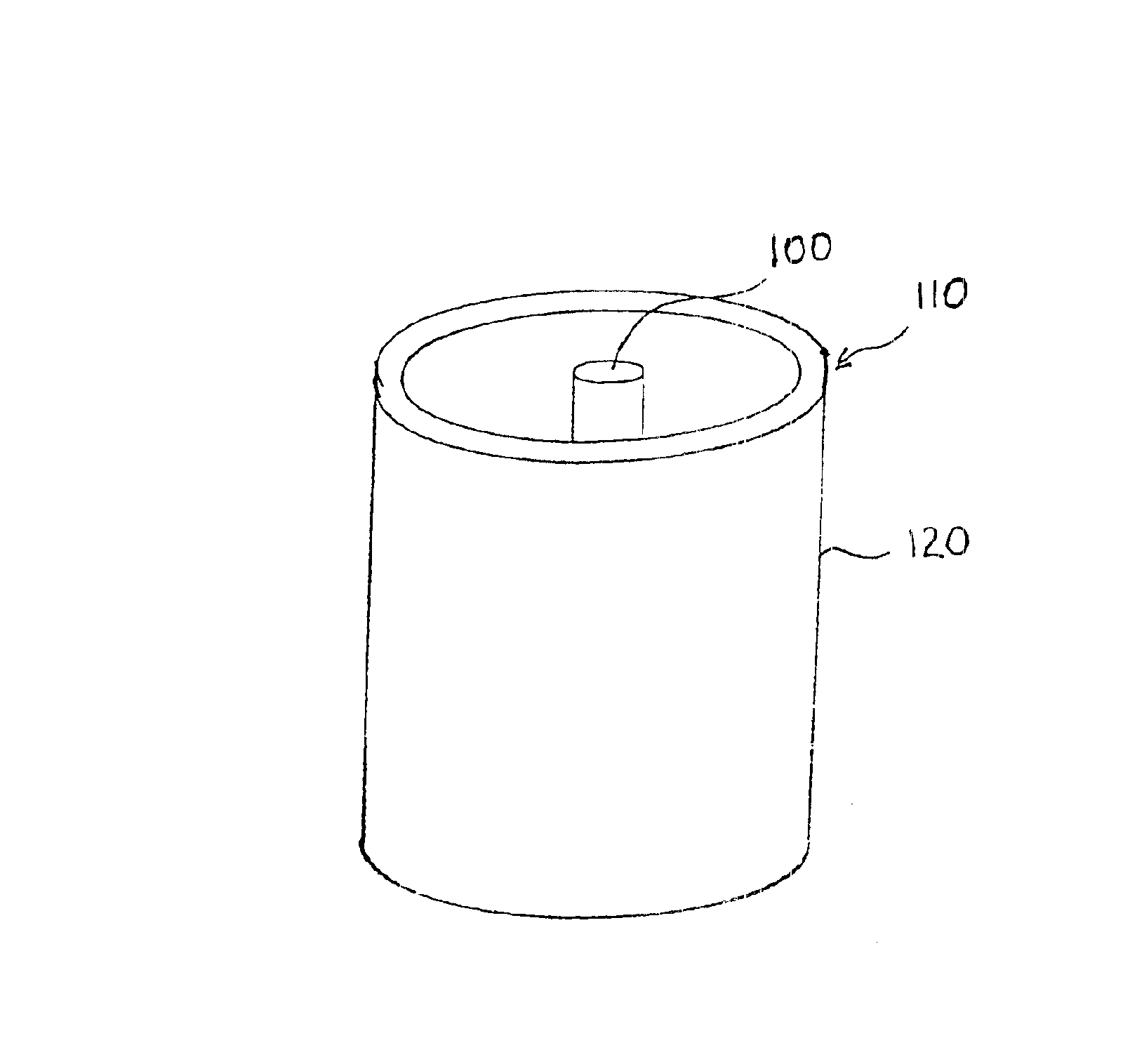
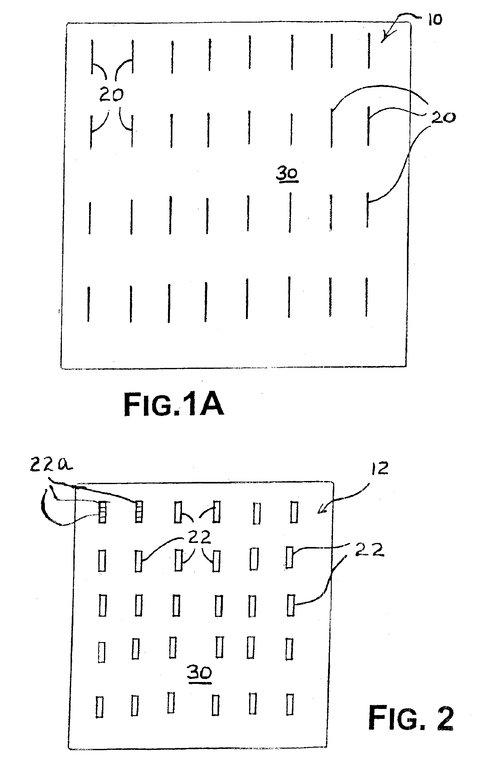
Referring now to the drawings, in which like reference numerals are used to refer to the same or similar elements, FIG. 1A shows an array 10 of linear variable conductive elements 20 on a dielectric surface 30. The array 10 of FIG. 1A represents the foundation of the steerable antennas described herein. The array is configurable, by energizing all, none or specific ones of the elements 20, to filter selected frequencies of electromagnetic radiation, including in the optical range. It should be noted that elements 20 are dipoles. Feeds (not shown) are provided to each element 20 in the array 10 using connectors which are electrically small with respect to the dipole and relevant frequencies.

Depending on the frequency range desired to be affected by the array 10, the variable conductive elements 20 are formed by different structures. In the RF frequency range, the variable conductive elements 20 are a gaseous plasma-containing element, such as a plasma tube. In the millimeter infrared...


PUM


Abstract

An reconfigurable array of variable conductive elements is provided for reflecting, filtering and steering electromagnetic radiation across a wide range of frequencies. The reconfigurable array is combined with a transmitting antenna to make a steerable antenna. The reconfigurable array surrounds the transmitting antenna and reflects all transmissions except on selected radials where apertures in the reconfigurable array are formed for permitting transmission lobes. The reconfigurable arrays can be arranged in stacked layers to make transceiving multiband antennas. Communications networks using the steerable antennas nas and arrays are also disclosed.

Description

FIELD AND BACKGROUND OF THE INVENTIONThe present invention relates generally to the field of antennas and in particular to a new and useful directional antenna that is steerable by configuring a switched plasma, semiconductor or optical crystal screen surrounding a central transmitting antenna.Traditionally, antennas have been defined as metallic devices for radiating or receiving radio waves. Therefore, the paradigm for antenna design has traditionally been focused on antenna geometry, physical dimensions, material selection, electrical coupling configurations, multi-array design, and / or electromagnetic waveform characteristics such as transmission wavelength, transmission efficiency, transmission waveform reflection, etc. As such, technology has advanced to provide many unique antenna designs for applications ranging from general broadcast of RF signals to weapon systems of a highly complex nature.Included among these antennas are omnidirectional antennas, which radiate electromag...

Claims


Application Information

Patent Timeline
Patent Type & Authority Patents(United States)
IPC IPC(8): H01Q1/38H01Q15/00H01Q15/02H01QH01Q1/36H01Q3/46H01Q19/32
CPCH01Q1/366H01Q15/006H01Q19/32H01Q3/46
Inventor ANDERSON, THEODORE R.
Owner ANDERSON THEODORE R
Why Eureka
Try Eureka