Method, related equipment and system for measuring channel state information

A channel state information and measurement method technology, applied in the field of channel state information measurement, can solve the problems of reducing system data transmission capacity, terminals cannot receive correctly, data cannot be fully utilized, etc.

Active Publication Date: 2012-08-01
HUAWEI TECH CO LTD
View PDF3 Cites 20 Cited by
  • Summary
  • Abstract
  • Description
  • Claims
  • Application Information

AI Technical Summary

Problems solved by technology

[0009] The inventors have found in practice that there are differences in the measurement capabilities and receiving capabilities of terminals served by the same base station, and the accuracy of the Rank value measured by each terminal is different. The measurement of CQI and PMI will also have an impact, resulting in the accuracy of CSI reported by each terminal to the base station. The base station cannot judge the difference in the measurement capability and receiving capability of each terminal, so the base station decides to send data to the terminal according to the CSI. There may be deviations in the transmission mode, so that the terminal cannot receive data correctly or cannot make full use of transmission resources, thereby reducing the data transmission capacity of the system

Method used


Image

  • Method, related equipment and system for measuring channel state information
  • Method, related equipment and system for measuring channel state information
  • Method, related equipment and system for measuring channel state information

Examples


Embodiment 1

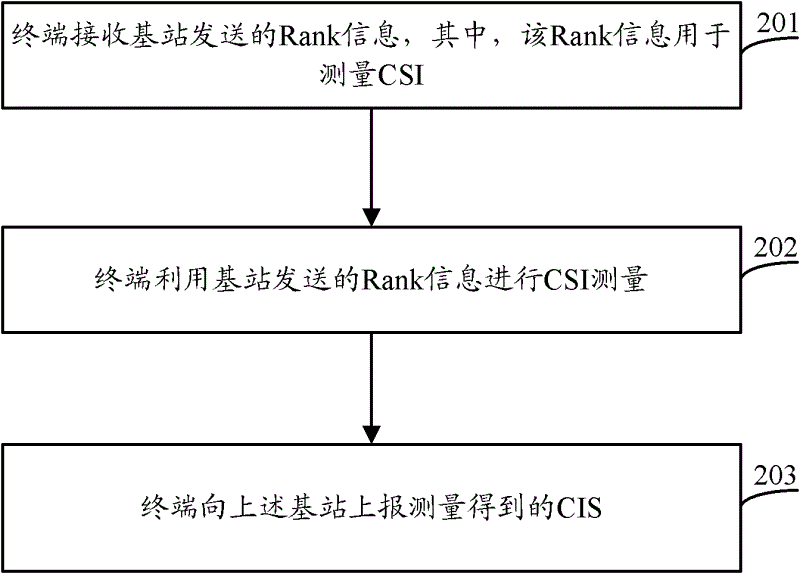
[0030] see figure 2 , figure 2 It is a schematic flowchart of a CSI measurement method provided by an embodiment of the present invention. Wherein, the method may include the following content.

[0031] 201. The terminal receives Rank information sent by a base station, where the Rank information is used to measure CSI.

[0032] In the embodiment of the present invention, the terminal may be a mobile phone, a personal digital assistant (PDA), etc., or other communication equipment, which is not limited in the embodiment of the present invention.

[0033] Wherein, in step 201 above, receiving the Rank information sent by the base station by the terminal may be implemented in various ways, and the embodiments of the present invention will be described in detail later.

[0034] 202. The terminal uses the Rank information sent by the base station to perform CSI measurement.

[0035] In the embodiment of the present invention, the Rank information sent by the base station can...

Embodiment 2

[0105] see Figure 5 , Figure 5 It is a schematic flowchart of another CSI measurement method provided by an embodiment of the present invention. Among them, the method may include the following:

[0106] 501. The base station determines Rank information corresponding to the terminal, where the Rank information is used to measure CSI.

[0107] For example, the base station may determine the Rank information corresponding to each terminal according to empirical values, or determine the Rank information corresponding to each terminal according to a preset strategy, which is not limited in this embodiment of the present invention. Wherein, the Rank information corresponding to each terminal determined by the base station may be the same or different.

[0108] 502. The base station sends rank information corresponding to the terminal to the terminal.

[0109] As an optional implementation manner, the base station may send the Rank information corresponding to the terminal to ...

Embodiment 3

[0121] see Figure 6 , Figure 6 It is a schematic structural diagram of a terminal device provided by an embodiment of the present invention. The terminal device provided in Embodiment 3 of the present invention may be used to implement the method for measuring CSI described in Embodiment 1 above. Such as Figure 6 As shown, the terminal device may include: a receiving unit 601 , a measuring unit 602 and a sending unit 603 . Wherein, the receiving unit 601 receives the Rank information sent by the base station, wherein the Rank information is used to measure CSI; the measuring unit 602 uses the Rank information received by the receiving unit 601 to perform CSI measurement; the sending unit 603 reports to the base station that the measuring unit 602 measures Get the CSI.

[0122] As an optional implementation manner, the receiving unit 601 may receive Rank information delivered by the base station through DCI; wherein, the Rank information may be expressed in a bit form. ...


PUM


Abstract

The embodiment of the invention relates to the field of communication technology, disclosing a method, related equipment and a system for measuring channel state information, wherein the method for measuring the channel state information comprises the steps that: a terminal receives rank information sent by a base station, wherein the rank information is used for measuring the channel state information; the terminal measures the channel state information by using the rank information; and the terminal reports the measured channel state information to the base station. By implementing the embodiment of the invention, the accuracy of channel state information reported by the terminal can by improved, so that the deviation in the transmission way for sending data to the terminal determined by the base station is reduced, and that the data transmission capacity of the system is improved.

Description

technical field [0001] The invention relates to the technical field of communication, in particular to a measurement technology of channel state information. Background technique [0002] In a long term evolution (Long Term Evaluation, LTE) system, multiple data symbols can be simultaneously transmitted between a terminal and a base station through multiple transmit antennas. Wherein, the above-mentioned number of simultaneously transmitted data symbols is called rank (Rank) or the number of transmission layers. For ease of description, Rank is used to represent the number of data symbols simultaneously transmitted through multiple transmit antennas. [0003] In the LTE system, the terminal needs to report channel state information (Channel State Information, CSI) to the base station, where the CSI reported by the terminal may include rank indication (Rank Indication, RI), channel quality indication (Channel Quality Indication, CQI) and precoding One or more of the matrix ...

Claims


Application Information

Patent Timeline
Patent Type & Authority Applications(China)
IPC IPC(8): H04W24/10H04L1/00
Inventor 高驰吴强周永行孙卫军
Owner HUAWEI TECH CO LTD
Why Eureka
Try Eureka