Permanent magnet synchronous motor fault simulation system and fault diagnosis method

A permanent magnet synchronous motor, fault simulation technology, applied in the direction of motor generator testing, measuring electricity, measuring electrical variables, etc., can solve problems such as high cost

Inactive Publication Date: 2019-12-27
HARBIN UNIV OF SCI & TECH
View PDF6 Cites 1 Cited by
  • Summary
  • Abstract
  • Description
  • Claims
  • Application Information

AI Technical Summary

Problems solved by technology

[0002] With the continuous improvement of modern industrial electrification and automation, the requirements for the reliability of the electric drive system are also getting higher and higher. In order to improve the reliability of the system, it is necessary to conduct fault research on the motor and its drive system, and conventional fault experiments require more high price

Method used


Image

  • Permanent magnet synchronous motor fault simulation system and fault diagnosis method
  • Permanent magnet synchronous motor fault simulation system and fault diagnosis method
  • Permanent magnet synchronous motor fault simulation system and fault diagnosis method

Examples


Embodiment 1

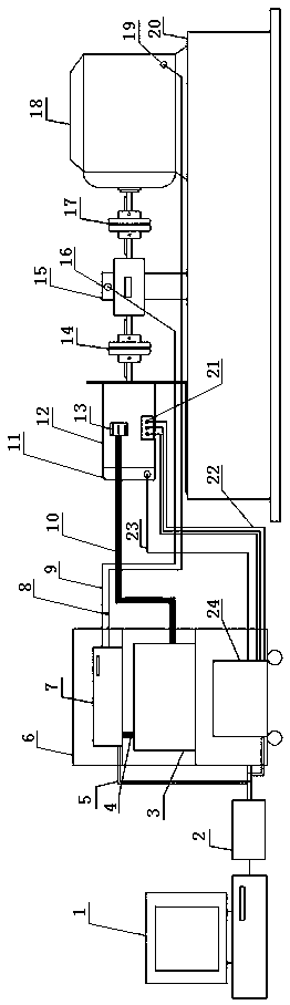
[0020] A kind of permanent magnet synchronous motor fault simulation system, its composition comprises: permanent magnet synchronous motor 12, described permanent magnet synchronous motor one end is equipped with rotor position detector 11, and the other end is connected with torque sensor 15 by coupling I14, The torque sensor is connected to the dynamometer 18 through the coupling II17, the lower end of the dynamometer has a signal output terminal 19, and is transmitted to the data acquisition and control system 7 through the signal feedback cable 8, and the rotor The position detector is transmitted to the motor controller 24 through the rotor position signal rotor position signal line 23, the fault point 13 on the permanent magnet synchronous motor is connected with the short circuit fault simulation actuator 3 through the cable 10, and the permanent magnet synchronous The power input terminal 21 under the motor is connected with the motor controller through a cable 22 .

Embodiment 2

[0022] According to the permanent magnet synchronous motor fault simulation system described in embodiment 1, the motor controller, the short-circuit fault simulation actuator, and the data acquisition and control system are installed in the cabinet 6 in sequence, and the data The acquisition and control system is connected with the short-circuit fault simulation actuator through the control line, the data acquisition and control system 4 is connected with the CAN analyzer 2 through the CAN bus 5, and the CAN analyzer is connected with the industrial computer through the USB interface 1 connection, the CAN analyzer is connected with the motor controller through the CAN bus.

Embodiment 3

[0024] According to the permanent magnet synchronous motor fault simulation system described in embodiment 1, the described torque sensor has a signal output terminal 16 and passes through the torque signal feedback cable 9 to the described data acquisition and control system, and the described dynamometer . The torque sensor is fixed on the upper plane of the base 20 through a bracket, and the right end of the permanent magnet synchronous motor is fixed on the base through a bracket.


PUM


Abstract

A PMSM fault simulation system and a fault diagnosis method are provided; along with improvement of industrial electrification and automation levels, an electrical transmission system reliability is getting higher and higher, and fault research for a motor driving system is needed, yet, normal fault experiments are high in costs; the PMSM fault simulation system comprises a PMSM (12); one end of the PMSM is provided with a rotor position detector (11), and the other end is connected with a torque sensor (15) via a shaft coupling I (14); the torque sensor is connected with a dynamometer (18) via a shaft coupling II (17); the bottom of the dynamometer is provided with a signal output port (19), and is transmitted to a data acquisition and control system (7) via a signal feedback cable (8); the rotor position detector is transmitted to a motor controller (24) via a rotor position signal line (23); a fault point (13) on the PMSM is connected with a short circuit fault simulation performer(3) via a cable (10). The method is applied to the PMSM fault simulation system.

Description

Technical field: [0001] The invention relates to a permanent magnet synchronous motor fault simulation system and a fault diagnosis method. Background technique: [0002] With the continuous improvement of modern industrial electrification and automation, the requirements for the reliability of the electric drive system are also getting higher and higher. In order to improve the reliability of the system, it is necessary to conduct fault research on the motor and its drive system, and conventional fault experiments require more high price. The permanent magnet synchronous motor system has become one of the hotspots in the field of contemporary electrical transmission due to its simple and firm structure, excellent speed regulation performance and many other advantages. Therefore, building a reasonable fault simulation platform has become the basis for motor fault diagnosis. Through the fault simulation platform , can observe and simulate the operating state characteristics ...

Claims


Application Information

Patent Timeline
Patent Type & Authority Patents(China)
IPC IPC(8): G01R31/34
CPCG01R31/343G01R31/346
Inventor 周凯臧经伦金宁治刘金凤王旭东
Owner HARBIN UNIV OF SCI & TECH
Why Eureka
Try Eureka