Shaft type adjustable camera support

A camera and shaft-type technology, which is applied in the direction of machines/brackets, supporting machines, magnetic objects, etc., can solve the problems that users are difficult to adjust the angle, the size of the camera is small, and the infinite adjustment cannot be realized, so that it is not easy to radially shift, Eliminate the effect of back-moving, circumferential relative position stabilization

Pending Publication Date: 2018-10-23
杭州国迈电子科技有限公司
View PDF0 Cites 0 Cited by
  • Summary
  • Abstract
  • Description
  • Claims
  • Application Information

AI Technical Summary

Problems solved by technology

However, there are still some deficiencies in the above-mentioned camera support structures: the size of the cameras is relatively small, and small angle changes often cause large changes in the mapped images. Adjustment needs, and the above structure has a certain amount of elastic force, and it is inevitable that it will rebound under the action of elastic force during fine-tuning, so that users often find it difficult to adjust to the ideal angle with all their efforts.
However, there is a contradictory relationship between multi-angle adjustment and fine-tuning rebound in the field, which is a technical problem. It is difficult to ensure that the position will not be affected by external forces after the conventional selection removes the elastic parts. Although it can solve the problem of springback and external force influence, it cannot realize infinite adjustment

Method used


Image

  • Shaft type adjustable camera support
  • Shaft type adjustable camera support
  • Shaft type adjustable camera support

Examples


Embodiment 1

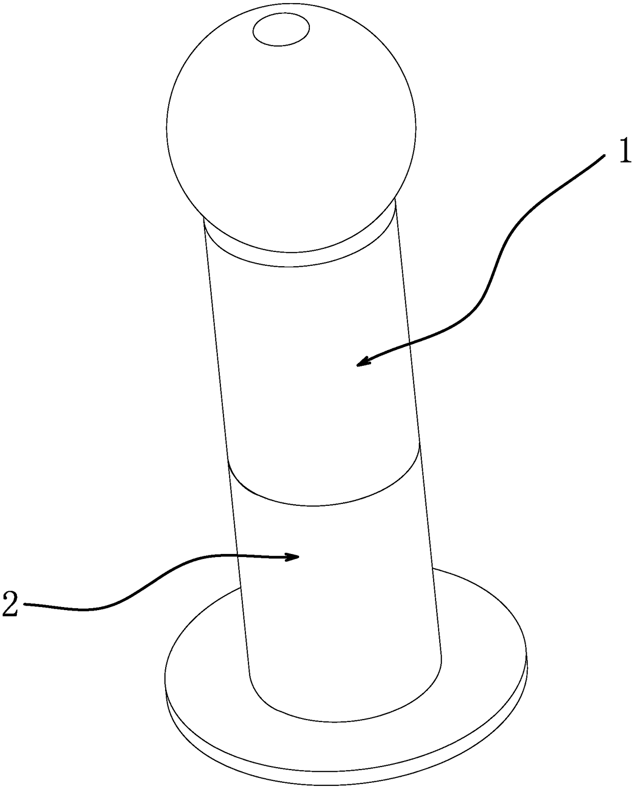
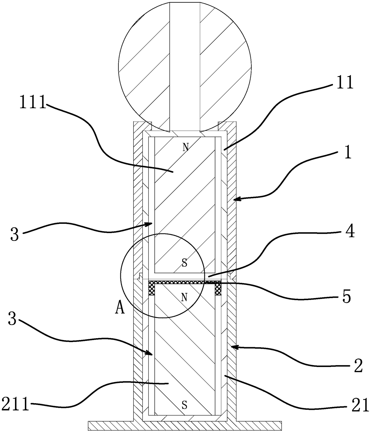
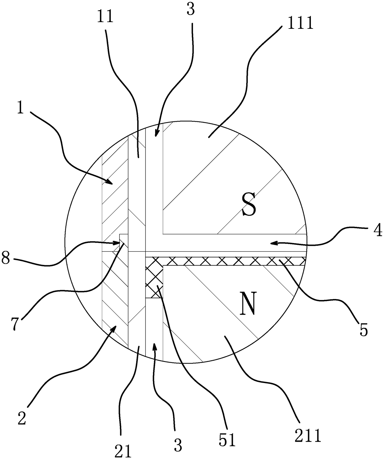
[0030] Such as Figure 1-4As shown, the shaft-type adjustable camera bracket includes an upper shaft 1 and a lower shaft 2 arranged axially opposite each other. The lower end surface of the upper shaft 1 is in close contact with the upper end surface of the lower shaft 2. Rotate in the vertical direction, the upper end surface of the lower shaft 2 and the lower end surface of the upper shaft 1 are respectively embedded with a magnetic conduction bowl 1 21 and a magnetic conduction bowl 2 11 which are axially oppositely arranged, and the open end surface of the magnetic conduction bowl 1 21 It abuts against the open end face of the magnetic conduction bowl 2 11 and forms a seal. A cylindrical permanent magnet 211 is coaxially fixed inside the magnetic conduction bowl 1 21, and a cylindrical permanent magnet 211 is coaxially fixed inside the magnetic conduction bowl 2 11. The second permanent magnet 111, the second permanent magnet 111 and the first permanent magnet 211 are coax...

Embodiment 2

[0033] Such as Figure 5 As shown, the present embodiment is basically the same as the first embodiment, except that: in the shaft-type adjustable camera bracket, the top surface of the permanent magnet 1 211 is in close contact with the permanent magnet 2 111 . By arranging the first permanent magnet 211 and the second permanent magnet 111 to be in close contact, the maximum axial force can be achieved, the connection and the direct alignment effect between the upper shaft 1 and the lower shaft 2 can be ensured, and the damping in the adjustment process can be increased to facilitate precise adjustment. Epoxy resin 6 is poured in the annular space 3, the permanent magnet one 211 is fixedly connected with the magnetic conduction bowl one 21 through the epoxy resin 6, and the permanent magnet two 111 is fixedly connected with the magnetic conduction bowl two 11 through the epoxy resin 6. By pouring epoxy resin 6 in the annular space 3, the axial and radial positions of permanen...


PUM


Abstract

The invention provides a shaft type adjustable camera support, and belongs to the technical field of articles of daily use. The shaft type adjustable camera support solves the technical problem that an existing camera support structure inevitably generates springback under the elastic force effect during fine adjustment, and consequently the ideal angle can be difficult to adjust even though a user makes much ado about it. The shaft type adjustable camera support comprises an upper shaft and a lower shaft which are oppositely arranged in the axial direction, the upper shaft can rotate relativeto the lower shaft around the vertical direction, the upper end face of the lower shaft and the lower end face of the upper shaft are internally provided with a first magnetism conduction bowl and asecond magnetism conduction bowl which are oppositely arranged in the axial direction in an embedded manner, the opening end face of the first magnetism conduction bowl abuts against the opening end face of the second magnetism conduction bowl to form sealing, a cylindrical first permanent magnet is coaxially and fixedly arranged in the first magnetism conduction bowl, and a cylindrical second permanent magnet is coaxially and fixedly arranged in the second magnetism conduction bowl, and the second permanent magnet and the first permanent magnet are coaxial and opposite and attract each other.According to the shaft type adjustable camera support, rotation is rigid sliding without springback, and attraction of magnetism conduction products around is not prone to occurrence.

Description

technical field [0001] The invention belongs to the technical field of daily necessities, and relates to a shaft-type adjustable camera bracket. Background technique [0002] Home computers have spread to thousands of households, and camera tools have become an important tool for people to use computers to communicate with the outside world. Some computer monitors have built-in camera devices. This kind of camera is highly integrated, but the shooting angle is fixed, which is often difficult to meet the needs of users The needs of various shooting angles. [0003] In order to solve the above problems, camera manufacturers have designed a variety of external camera devices, which can be conveniently placed at different positions on the host or desktop according to the needs of users, to achieve shooting from different angles. For example, some external cameras have connected The upper bracket and the lower bracket, the upper bracket can rotate relative to the lower bracket, ...

Claims


Application Information

Patent Timeline
Patent Type & Authority Applications(China)
IPC IPC(8): F16M11/24H01F7/02
CPCH01F7/021H01F7/0221F16M11/24
Inventor 周伟军吕文政周宋生杨家星
Owner 杭州国迈电子科技有限公司
Why Eureka
Try Eureka