
Single-screw carbon fiber mechanical lifting rod

A carbon fiber, lifting rod technology

Pending Publication Date: 2019-04-19
铁岭长天机电有限责任公司
View PDF1 Cites 0 Cited by
  • Summary
  • Abstract
  • Description
  • Claims
  • Application Information

AI Technical Summary

Problems solved by technology

[0010] 1. The connecting piece of the interlocking device between the pipes is a straight round rod-shaped radial pin hinged at one end of the lower lever inside the inner pipe and a circular pin hole of the adjacent outer round pipe. The radial pin is inserted into the pin hole by elasticity, so that the adjacent The radial connection process and interlocking of round pipes are not very reliable;
[0011] 2. The interlocking device between the pipes only has the connecting device between the radial pipes connected for lifting. There is no axial connecting device between the adjacent round pipes after the mechanical elevating rod is lowered. When the mechanical elevating rod rises again, the adjacent round pipes Due to the small gap, there will be close contact. This kind of close contact sometimes causes adjacent circular tubes to rise simultaneously due to friction without real connection. Because there is no real connection, after the contact and fit disappear, due to friction The circular tube that rises at the same time due to force will suddenly fall, and the collision caused by the sudden fall will damage the mechanical lifting rod

Method used


Image

  • Single-screw carbon fiber mechanical lifting rod
  • Single-screw carbon fiber mechanical lifting rod
  • Single-screw carbon fiber mechanical lifting rod

Examples


Embodiment Construction

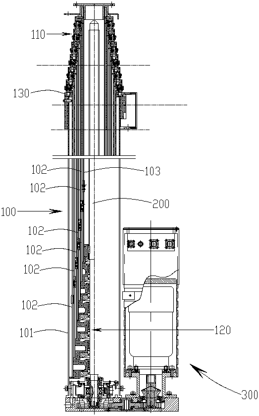
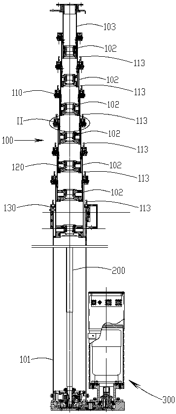
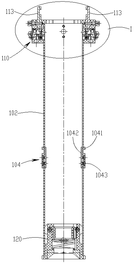
[0046] see figure 1 - Figure 28 , the single-screw carbon fiber mechanical lifting rod of the present invention includes a carbon fiber tube body 100, a lead screw 200 and a driving device 300 for driving the lead screw to rotate. The carbon fiber top tube 103 on the inner side and a plurality of carbon fiber inner tubes 102 located between the bottom tube and the top tube are composed of a circular lock seat 110, a top tube and the lower end of each inner tube outside the upper end nozzle of each inner tube. There is a silk nut sleeve 120 in the nozzle, and an annular upper sleeve 130 is installed outside the upper nozzle of the bottom tube. The left and right sides of the annular lock seat 110 are respectively provided with radial lock cavities 111. Correspondingly, The wall of the inner tube has a lock hole 1021 that communicates with the lock cavity. A lock sleeve 112 is embedded in the lock cavity. The lock sleeve has a lock sleeve baffle 1121 and two pieces perpendicul...


PUM


Abstract

The invention discloses a single-screw carbon fiber mechanical lifting rod. The mechanical lifting rod comprises a pipe body, a lead screw and a driving device for driving the lead screw to rotate; the pipe body is composed of a bottom pipe, a top pipe and a plurality of inner pipes; a circular ring-shaped lock base is arranged outside a pipe opening at the upper end of each inner pipe, and a nutsleeve is arranged in a pipe opening at the lower end of the top pipe and each inner pipe; a circular ring-shaped upper sleeve is arranged outside a pipe opening at the upper end of the bottom pipe, radial lock cavities are formed in the peripheries of the left side and the right side of the circular ring-shaped lock base respectively, a lock sleeve is embedded in each lock cavity, a radial slideblock and an axial stop block are arranged in each lock sleeve, and a swing block is installed on each radial slide block; a lock hook is installed on each circular ring-shaped lock base of the pipe opening at the upper end of the inner pipes except the inner pipe adjacent to the top pipe, a lock hook is also installed on the circular ring-shaped upper sleeve, and a locking hook hole is formed inthe lower surface of the corresponding circular ring-shaped lock base; and a radial sliding block limiting assembly is installed on the pipe wall at the lower part of each inner pipe and the pipe wallat the lower part of the top pipe except the inner pipe adjacent to the bottom pipe. According to the mechanical lifting rod, the radial connection between the round pipes can be realized after the rod is lifted,and the axial connection between the round pipes can be realized after the rod is descended.

Description

technical field [0001] The invention relates to a lifting rod, in particular to a single-screw carbon fiber mechanical lifting rod. Background technique [0002] In the prior art, Chinese patent ZL 98 2 38478.5 discloses a telescopic mechanical lifting rod with a single lead screw and multiple circular tubes, the mechanical lifting rod has a pipe body, a lifting driving device and an inter-tube interlocking device. [0003] The tube body is a plurality of circular tubes with diameters from large to small with the axes on the same line. Among the multiple circular tubes, the outermost circular tube is the bottom tube, and the innermost circular tube is the top tube. , the rest of the round tubes are inner tubes, the bottom tube is fixed on the base, the gap between the adjacent round tubes is the same, the outer walls of the top tube and the inner tube have guide keys along the axial direction, and the upper ends of the bottom tube and the inner tube have circular An annular...

Claims


Application Information

Patent Timeline
IPC IPC(8): B66F3/10B66F3/44
CPCB66F3/10B66F3/44
Inventor 李波王建军隋锷
Owner 铁岭长天机电有限责任公司
Learn More