Hydraulic buffer structure for hydraulic suspension passive shutdown experimental device

A technology of buffer structure and experimental device, which is applied in the direction of reactor, nuclear power generation, nuclear reaction control, etc., can solve the problems of large influence of suspension stability of control rod, increased uncertainty of experimental data measurement, unfavorable test section and centrifugal pump safety, etc. , to achieve the effect of improving suspension stability, uniform coolant velocity distribution, and reducing rod drop time

Active Publication Date: 2018-10-23
XI AN JIAOTONG UNIV
View PDF9 Cites 11 Cited by
  • Summary
  • Abstract
  • Description
  • Claims
  • Application Information

AI Technical Summary

Problems solved by technology

However, in its experiments and calibration calculations, it was found that this design has a greater impact on the suspension stability of the control rods due to uneven water intake, which increases the uncertainty of the experimental data measurement, and there will be obvious water when the rods are dropped. Hammer effect, which is not conducive to the safety of the test section and the centrifugal pump

Method used


Image

  • Hydraulic buffer structure for hydraulic suspension passive shutdown experimental device
  • Hydraulic buffer structure for hydraulic suspension passive shutdown experimental device

Examples


Embodiment Construction

[0030] In order to make the above objects, features and advantages of the present invention more comprehensible, the present invention will be further described in detail below in conjunction with the accompanying drawings.

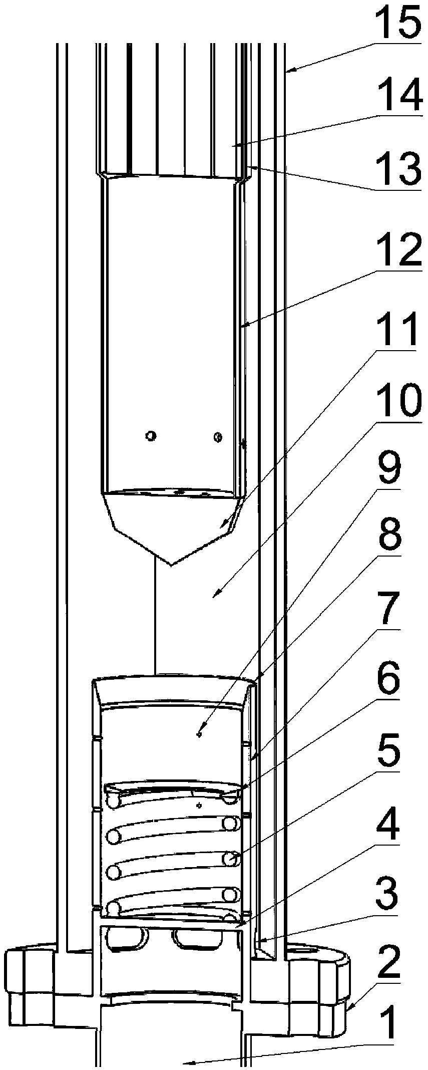
[0031] refer to figure 2 , a hydraulic buffer structure for a hydraulic suspension type passive shutdown experimental device according to the present invention, comprising an inlet pipe flange 2, a water inlet hole 3, a compression spring base baffle plate 4, a cylindrical compression spring 5, Buffer gasket 6, hydraulic buffer cylinder 7, tapered through hole 8, pressure relief hole 9, lower end cover 11, damping block 12, passive shutdown rod model middle sleeve 13 and visualization sleeve 15.

[0032] figure 2 Shown is the structural representation of the hydraulic buffer and supporting parts of the present invention, the hydraulic buffer cylinder 7 is vertically welded on the center of the upper end face of the inlet pipe flange 2, and the hexagona...


PUM


Abstract

The invention discloses a hydraulic buffer structure for a hydraulic suspension passive shutdown experimental device. The hydraulic buffer structure comprises a hydraulic buffer cylinder mounted on aninlet pipe flange, a compression spring and a base baffle thereof, a visual casing pipe and a passive shutdown rod lower end plug structure. The hydraulic buffer cylinder is divided into an upper part and a lower part through the compression spring base baffle. The lower part is provided with a group of water inlet holes arranged at equal intervals along the circumferential direction. The upper part is provided with three groups of pressure relief holes equally spaced in the circumferential direction. The tail of the upper part is processed to form a tapered through hole. The passive shutdownrod lower end plug structure comprises a damping block and a conical lower end cover. The damping block is provided with a group of through holes at equal intervals along the circumferential direction. The upper part of the damping block is connected to a passive shutdown rod middle casing pipe. Through combination of the necking transition design and the compression spring, the total rod fallingtime of the passive shutdown rod is significantly reduced. The annular gap water inlet design realizes uniform coolant velocity distribution and improves the suspension stability of the passive shutdown rod.

Description

technical field [0001] The invention belongs to the technical field of performance verification test research on protection system equipment of a nuclear power plant, and in particular relates to a hydraulic buffer structure for a hydraulic suspension type passive shutdown experimental device. technical background [0002] The hydraulic suspension passive shutdown experimental device is a platform for experimental research on the dynamic characteristics of the sodium-cooled fast reactor hydraulic suspension passive shutdown device using water as a substitute for sodium. The hydraulic suspension passive shutdown device is an emergency shutdown protection device for sodium-cooled fast reactors. When accidents and other working conditions cause the coolant flow rate to drop enough to keep the control rods suspended, the control rods will drop to the core position to shut down the reactor. It can be seen from the working principle that the action of the suspended control rod is...

Claims


Application Information

Patent Timeline
Patent Type & Authority Applications(China)
IPC IPC(8): G21C7/20
CPCG21C7/20Y02E30/30
Inventor 巫英伟宋健苏光辉田文喜秋穗正
Owner XI AN JIAOTONG UNIV
Why Eureka
Try Eureka