Connector

A technology for connectors and matching connectors, which is applied in the direction of connection, parts of connection devices, contact parts, etc., can solve the problems of deformation and separation of the elastic part 840

Active Publication Date: 2018-10-23
JAPAN AVIATION ELECTRONICS IND LTD +1
View PDF7 Cites 4 Cited by
  • Summary
  • Abstract
  • Description
  • Claims
  • Application Information

AI Technical Summary

Problems solved by technology

However, there is a possibility that if the mating connector 900 is pulled up in an attempt to forcibly disengage the connector 800 in the mating state where the connector 800 is mated with the mating connector 900, the mating connector 900 may be caused by the movement of the locking portion 842. The elastic portion 840 is deformed and disengaged from the connector 800

Method used


Image

  • Connector
  • Connector
  • Connector

Examples


no. 1 example

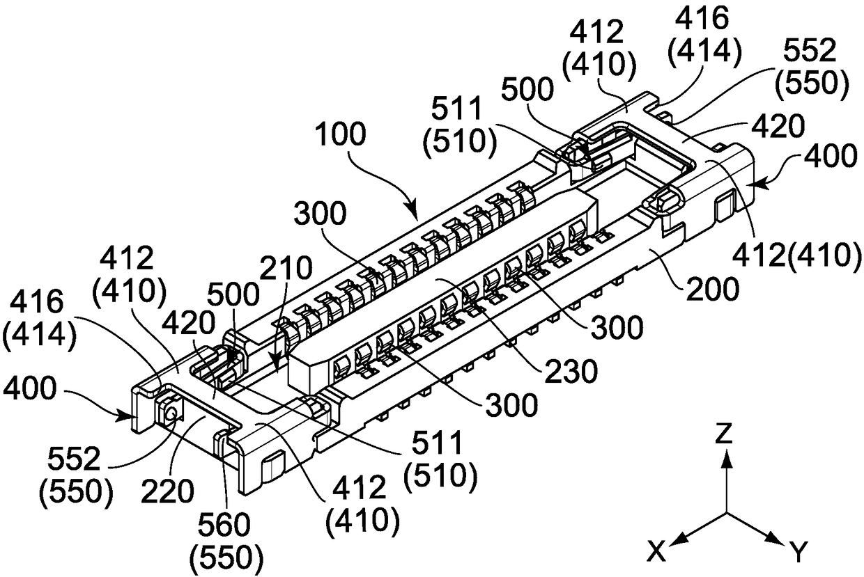
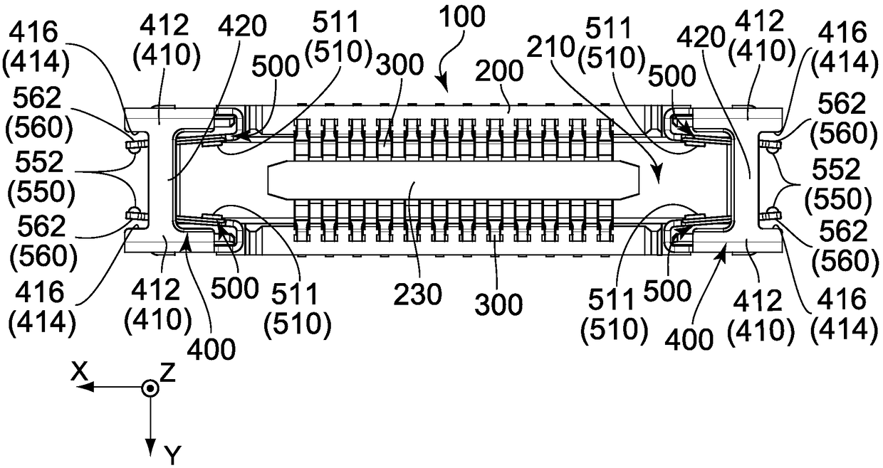
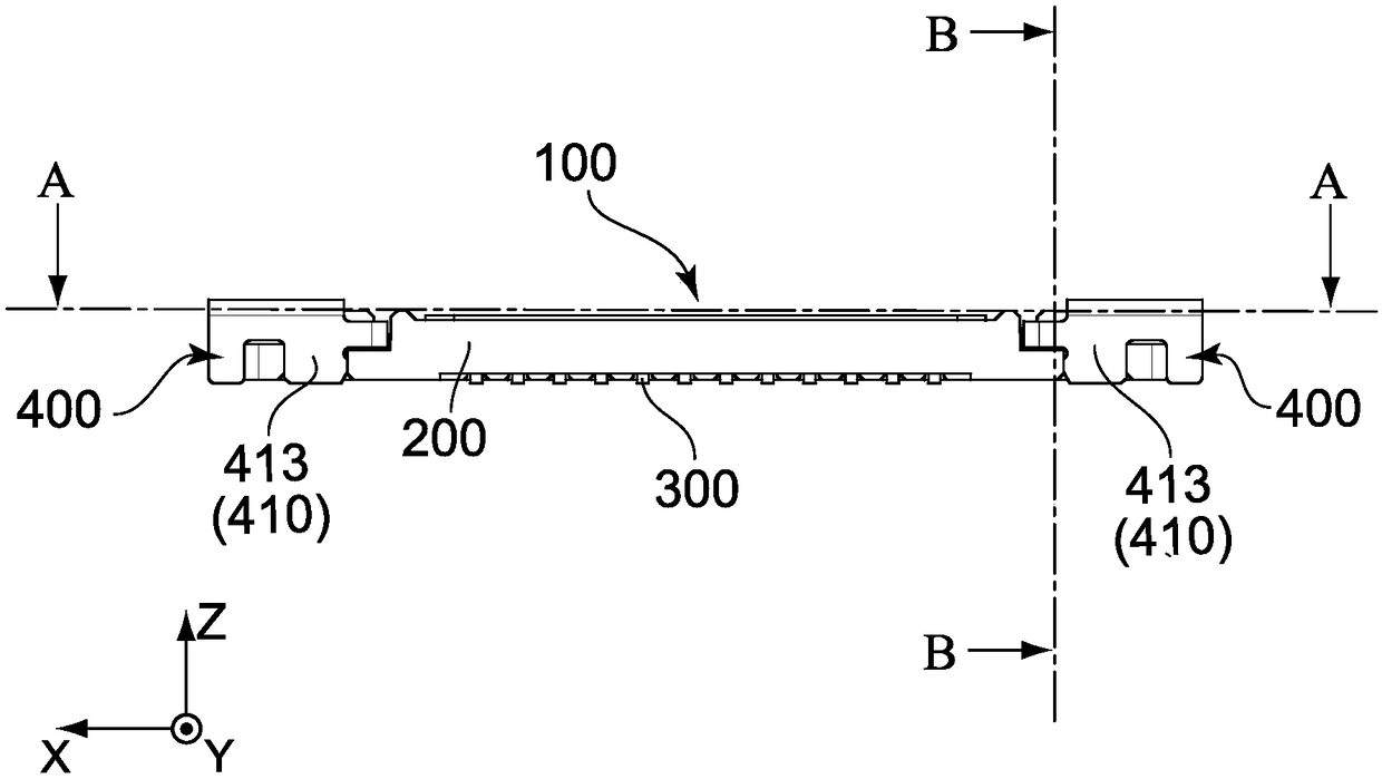
[0046] refer to figure 1 , Figure 12 , Figure 16 and Figure 17 , the connector 100 of the first embodiment of the present invention is installed on the object (not shown) in the up-down direction, and can be matched with the matching connector 700 in the up-down direction. In this embodiment, the up-down direction is the Z direction. Further, in the present embodiment, it is assumed that upward is the positive Z direction, and downward is the negative Z direction.

[0047] refer to Figure 12 to Figure 15 , the mating connector 700 of this embodiment includes a received portion 710 and four locked portions 722 .

[0048] like Figure 12 to Figure 15 As shown, the received part 710 in this embodiment has a matching housing 705 , two power terminals 715 and a plurality of matching terminals 730 .

[0049] like Figure 12 to Figure 15 As shown, the matching housing 705 has a substantially rectangular parallelepiped shape elongated in a first direction perpendicular to...

no. 2 example

[0076] refer to Figure 22 to Figure 32 , the connector 100A of the second embodiment of the present invention is an improvement of the connector 100 of the first embodiment described above. The connector 100A differs from the connector 100 only in the structure of the additional member 400A and its surrounding components. exist Figure 22 to Figure 32 in, and already in Figure 1 to Figure 11 Components that are the same as those described in are described using the same reference numerals; descriptions about these components will be omitted. For example, the terminal 300 of the connector 100A is the same as the terminal 300 of the first embodiment described above. Likewise, the structural relationship between the terminal 300 of the connector 100A and the housing 200A is the same as the structural relationship between the terminal 300 of the connector 100 and the housing 200 described above. For the directions and orientations in this embodiment, the same expressions as ...


PUM


Abstract

A connector is mountable on an object in an up-down direction and mateable with a mating connector along the up-down direction. The mating connector comprises four locked portions. The connector comprises two additional members. Each of the additional members comprises two regulation mechanisms. Each of the regulation mechanisms comprises a spring portion, an operation portion, a first regulatingportion, and a second regulating portion. The spring portion has a lock portion. The operation portion has a first regulated portion. One of the spring portion and the operation portion is provided with a second regulated portion. An upward movement of the lock portion is regulated when the first regulated portion is moved upward in the up-down direction to abut against the first regulating portion. The second regulating portion is brought into contact with the second regulated portion to regulate an outward movement of the lock portion in the second direction when the lock portion receives anupward force under a state where the first regulated portion abuts against the first regulating portion.

Description

technical field [0001] The present invention relates to a connector which is mounted on an object and mates with a mating connector. Background technique [0002] like Figure 33 to Figure 35 As shown, Patent Document 1 discloses a connector 800 which is mounted on an object 860 in the up-down direction (Z direction) and can be mated with a mating connector 900 in the up-down direction (Z direction). The mating connector 900 includes a received portion 910 and a locked portion 920 . In the mated state, the connector 800 is mated with the mating connector 900 with each locked portion 920 facing upward in the up-down direction (positive Z direction). The connector 800 includes a housing 810 , a plurality of terminals 820 and two additional members 830 . Each terminal 820 is held by the housing 810 . Each additional member 830 is held by the housing 810 . The housing 810 is formed with a receiving portion 812 . In the mating state in which the connector 800 and the mating ...

Claims


Application Information

Patent Timeline
Patent Type & Authority Applications(China)
IPC IPC(8): H01R13/639H01R13/627
CPCH01R13/6275H01R13/639H01R12/73H01R13/20H01R13/633H01R12/78H01R12/725H01R12/7005H01R13/635H01R13/6581
Inventor 芦部健太山口修平带金宏明西村贵行町原大介
Owner JAPAN AVIATION ELECTRONICS IND LTD
Why Eureka
Try Eureka