Butt joint type pneumatic pipe joint integration module

A technology of integrated modules and pneumatic tubes, applied in the direction of pipes/pipe joints/fittings, pipes, pipe components, etc., can solve the problems of inconvenient testing and maintenance, complex pneumatic pipelines, etc., to improve service life and solve complex pneumatic pipelines , Ease of use

Active Publication Date: 2015-06-17
温州金业气动科技有限公司
View PDF7 Cites 2 Cited by
  • Summary
  • Abstract
  • Description
  • Claims
  • Application Information

AI Technical Summary

Problems solved by technology

[0007] By adopting the above-mentioned technical scheme, the present invention sets the left mounting plate and the right mounting plate, and the left mounting plate and the right mounting plate are butt-connected, and when the two mounting plates are docked, the through holes corresponding to each other are connected together and connected Effectively seal at the place, and install pneumatic pipe joints at the through holes of the two mounting plates. The pneumatic pipe joints are located on the opposite side of the mounting plate. It is only necessary to insert the pneumatic pipe joint for one connection, and the later pipeline disconnection is controlled by docking or separating the left mounting plate and the right mounting plate, thereby avoiding frequent plugging and unplugging of the air pipe and effectively preventing the air pipe from connecting with the pneumatic pipe joint. Damage occurs at the joints, which improves the service life, and the invention can integrate many pneumatic pipelines into one for unified management and operation, which effectively solves the problem of complex pneumatic pipelines and inconvenient testing and maintenance of large-scale automation equipment in the prior art. Problems, more convenient to use, more convenient to use in large-scale automation equipment and pneumatic system testing equipment, etc.

Method used


Image

  • Butt joint type pneumatic pipe joint integration module
  • Butt joint type pneumatic pipe joint integration module
  • Butt joint type pneumatic pipe joint integration module

Examples


Embodiment Construction

[0034] refer to Figure 1 to Figure 11 The embodiment of the butt joint pneumatic pipe joint integrated module of the present invention will be further described.

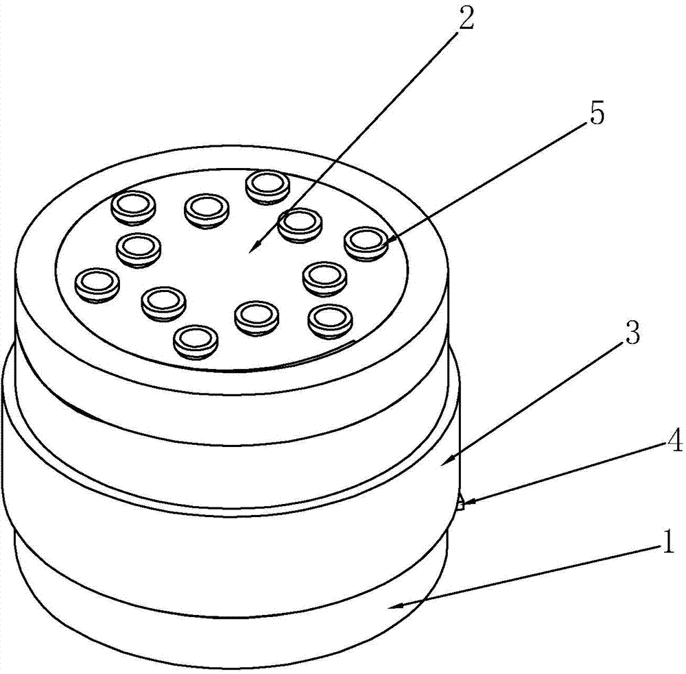
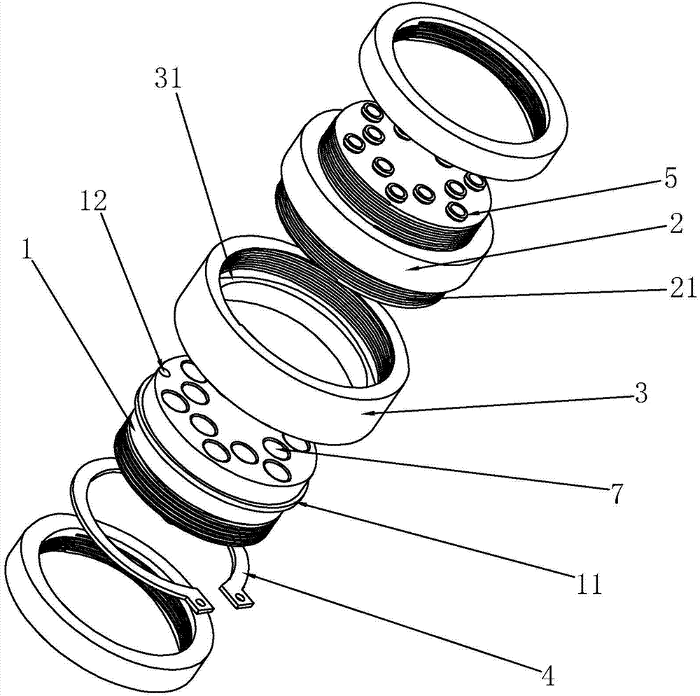
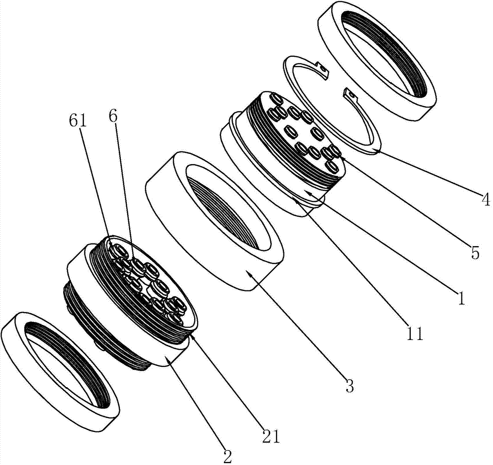
[0035] The integrated module of the docking type pneumatic pipe joint of the present invention, such as figure 1 As shown, it includes a left installation disk 1 and a right installation disk 2. The left installation disk 1 and the right installation disk 2 are provided with a number of through holes 7, and the positions of the through holes 7 of the two installation disks are all corresponding to each other. The left installation disk 1 and the right installation disk 2 are docked, and the through holes 7 corresponding to the left installation disk 1 and the right installation disk 2 can be detachably sealed and connected, and any installation disk is opposite to the other installation disk. Pneumatic pipe joints 5 are installed at the openings on the sides of the through holes 7 . The pneumatic pipe joint 5 ado...


PUM


Abstract

The invention discloses a butt joint type pneumatic pipe joint integration module. According to the technical scheme, the butt joint type pneumatic pipe joint integration module is characterized by comprising a left installation disc and a right installation disc; the left installation disc and the right installation disc are both provided with multiple through holes, and the through holes of the left installation disc correspond to the through holes of the right installation disc in position; the left installation disc and the right installation disc are arranged in a butt joint mode, and pneumatic pipe joints are installed on the sides, away from the joint portion, of the installation discs and located at the openings of the through holes; detachable sealing structures are arranged between the corresponding through holes of the left installation disc and the right installation disc. According to the butt joint type pneumatic pipe joint integration module, numerous pneumatic pipes can be uniformly managed, use is more convenient, it is unnecessary to perform operation on the pneumatic pipes frequently, the connecting stability between the pneumatic pipes and the pneumatic pipe joints is improved, and the service life is prolonged.

Description

technical field [0001] The invention relates to the field of pneumatic connectors, in particular to a pneumatic pipe joint integrated module. Background technique [0002] Pneumatic pipe joints have the characteristics of advanced structure, good performance and convenient use, and are widely used in hydraulic and pneumatic systems of various machinery. The most used in the prior art is the straight-through push-in pneumatic pipe joint. [0003] For example, the Chinese patent document with the application number 201320432005.2 discloses a quick-plug straight-through pneumatic pipe joint, including copper parts, collars, caps, sealing rings, collars and retaining springs. The copper parts form an inner cavity, and the sealing ring is tight. The fitting is set in the inner cavity of the copper piece, the collar is set in the lower end of the copper piece, the collar is set in the inner cavity of the collar and one end is connected with the sealing ring, and the upper end of ...

Claims


Application Information

Patent Timeline
Patent Type & Authority Applications(China)
IPC IPC(8): F16L41/03F16L15/00
CPCF16L39/00
Inventor 林南翔牛建
Owner 温州金业气动科技有限公司
Why Eureka
Try Eureka