
Method for measuring relative time delay between optical transmission channels operating in pulsed mode

A technology of transmission direction, pulsed light source, applied in the direction of measuring optics, devices for measuring time intervals, measuring devices, etc.

Active Publication Date: 2020-07-24
THALES SA
View PDF8 Cites 0 Cited by
  • Summary
  • Abstract
  • Description
  • Claims
  • Application Information

AI Technical Summary

Problems solved by technology

Furthermore, this delay measurement must be compatible with the optical phase measurement and control structure necessary for optical channel phase locking of the light source

Method used


Image

  • Method for measuring relative time delay between optical transmission channels operating in pulsed mode
  • Method for measuring relative time delay between optical transmission channels operating in pulsed mode
  • Method for measuring relative time delay between optical transmission channels operating in pulsed mode

Examples


Embodiment Construction

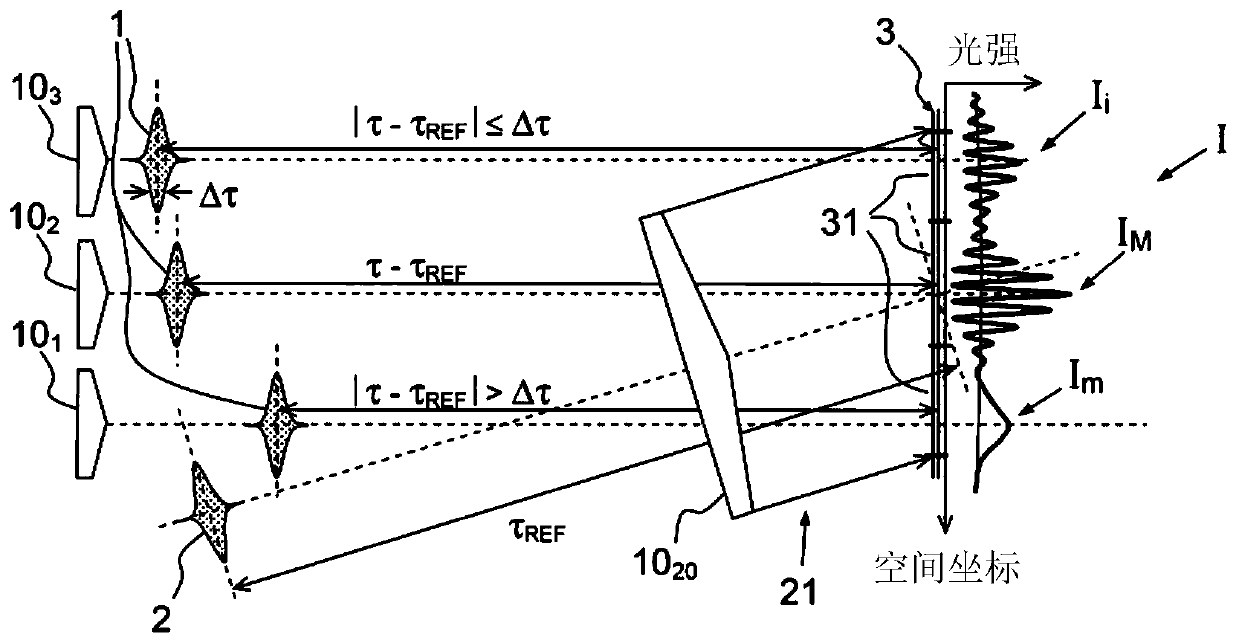
[0057] The solution presented takes as its basis the structure of co-phase measurements by interferometry techniques described in "Collective coherent phase combining of 64 fibers" published by J. Bourderionnet et al. in Opt Express. 19. In this configuration, the optical phase shift between transmission channels is obtained by analyzing the network of interference fringes between each beam and a common reference beam. The fringes are collectively recorded on the camera so that the entire phase shift is recorded on one image. In the pulse domain, asynchronous pulses, ie pulses that are not simultaneously present on the plane of the camera's sensor, will not interfere. Then measurement is impossible.

[0058] refer to figure 1 , an exemplary embodiment of a common measuring method is described. Assume that pulse 1 to be characterized is collimated and the pulses travel in the same direction; 3 pulses to be characterized are shown in the figure. The reference pulse 2 expands...


PUM


Abstract

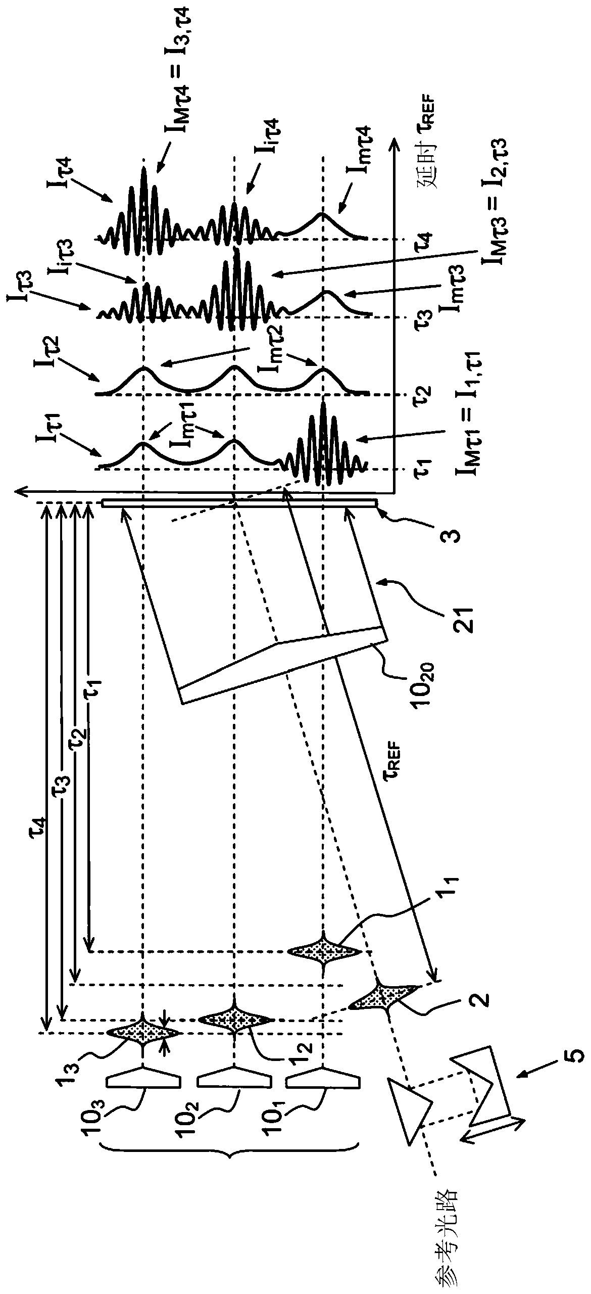
A method for measuring the delay between N pulses having a duration less than 100 picoseconds comprises the steps: collimated emission of the pulses having the same repetition frequency, emission of a reference pulse having the same repetition frequency capable of producing interference fringes with each of the pulses, for each of the pulses, detection, by a detector, of the coherent sum of this pulse with the reference pulse, this sum producing the interference fringes, the fringes originating from each of the pulses being distinguishable from one another. The reference pulse is emitted with an adjustable delay, and the method further comprises: for each delay, simultaneous measurement for the pulses of N contrasts of the interference fringes, for each of the pulses, a delay value between this pulse and the reference pulse is determined by the delay corresponding to the maximum contrast.

Description

Background technique [0001] Currently, the acquisition of high-power (or high-energy) and high-brightness laser light sources is limited by the luminous flux resistance of gain materials. One solution to this problem is to distribute the amplification into several stages of parallel gain media and then recombine them. [0002] The field of the invention relates to coherent recombination techniques for a large number of fundamental high power and / or high energy laser sources in ultrashort pulse sources (eg, with pulse widths less than 100 picoseconds). [0003] Compared with the continuous laser field, in the pulsed laser field, the recombination of such a laser source not only has additional requirements on the pulse in terms of phase, but also has additional requirements on the pulse in terms of synchronization. In other words, for the interaction to occur, the pulses must overlap in space and time. Therefore, the transmission time of the pulses in each transmission channel...

Claims


Application Information

Patent Timeline
Patent Type & Authority Patents(China)
IPC IPC(8): G01J9/02G01J11/00
CPCG01J9/02G01J11/00G01J2009/006G04F13/026H01S3/0057H01S3/2308
Inventor J·布尔德里奥内A·布里尼翁M·安捷-米尔热依
Owner THALES SA
Learn More