Supercharge Your Innovation With Domain-Expert AI Agents!

Substrate suction stage, substrate treatment apparatus, and substrate treatment method

A substrate processing method and adsorption table technology, which can be used in manufacturing tools, metal processing, laser welding equipment, etc., and can solve problems such as chip cracking, chip not being separated from the workbench, and reduced yield of qualified products

Active Publication Date: 2018-10-23
MITSUBISHI ELECTRIC CORP
View PDF9 Cites 1 Cited by
  • Summary
  • Abstract
  • Description
  • Claims
  • Application Information

AI Technical Summary

Problems solved by technology

If grinding debris adheres to the wafer, it will cause foreign matter or spots, reducing the yield of good products
In addition, if such water enters between the table and the back surface of the wafer, the wafer may not be separated from the table and the wafer may be cracked.

Method used


Image

  • Substrate suction stage, substrate treatment apparatus, and substrate treatment method
  • Substrate suction stage, substrate treatment apparatus, and substrate treatment method
  • Substrate suction stage, substrate treatment apparatus, and substrate treatment method

Examples


Embodiment approach 1

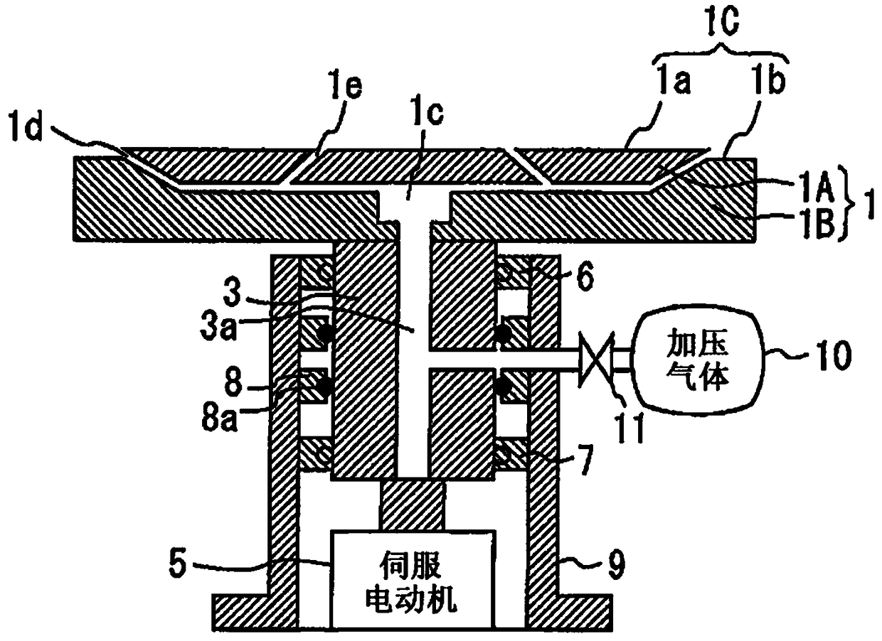
[0033] figure 1 It is a cross-sectional view of the substrate suction table according to Embodiment 1. The substrate suction table includes a substrate support unit 1 that supports a substrate. The substrate supporting part 1 has an upper surface 1C. The upper surface 1C includes a first upper surface 1a and a second upper surface 1b formed lower than the first upper surface 1a. A cavity 1c is formed inside the substrate support portion 1 . The cavity 1c is located substantially in the center of the substrate support portion 1 .

[0034] In the substrate supporting part 1, a discharge hole 1d extending from the cavity 1c to the upper surface 1C and an adsorption hole 1e connecting the discharge hole 1d to the upper surface 1C are formed. The discharge hole 1d is connected to the cavity 1c, and is also connected to the stepped portion between the first upper surface 1a and the second upper surface 1b. The adsorption hole 1e is formed in the first upper surface 1a. The ads...

Embodiment approach 2

[0055] Figure 10 It is a plan view of the second part 1B according to Embodiment 2. The second portion 1B of the substrate supporting portion 1 is formed in a circular shape in plan view. Figure 10 The shape of the slot 1i of part 2 1B with image 3 The slot 1f is different. The groove 1i is linear in a region close to the cavity 1c, but is formed in a curved line in a region far from the cavity 1c. According to this curved portion, a component advancing in a tangential direction to the outer edge of the second portion 1B can be given to the airflow ejected from the ejection hole 1d.

[0056] Figure 11 It is a diagram showing the flow of gas inside and outside the discharge hole 1d when the pressurized gas is supplied to the cavity 1c by arrows. The direction of the arrow 46 indicates the traveling direction of the gas ejected from the ejection hole 1d, and the length of the arrow 46 indicates the velocity of the gas. In addition, the curve 46a represents the velocity...

Embodiment approach 3

[0061] Figure 13 It is a cross-sectional view of the substrate suction table according to Embodiment 3. The first portion 1A of the substrate support unit 1 includes a spacer 50 . Below the partition 50 there is a part of the discharge hole 1d, and above the partition 50 there is an adsorption hole 1e. The adsorption hole 1e is composed of a parallel flow path 1k connected to the discharge hole 1d and extending parallel to the discharge hole 1d, and a connecting flow path 1j connecting the parallel flow path 1k with the substrate support portion 1. 1C connection on the upper surface. The parallel flow path 1k has a region on the side of the cavity 1c and a region on the outer edge side of the substrate supporting part 1 . The area on the outer edge side is connected to the discharge hole 1d, and the area on the cavity 1c side is connected to the connection channel 1j.

[0062] Figure 14 It is a plan view of the substrate suction table according to Embodiment 3. Figure...


PUM


Abstract

A substrate suction stage of the present invention is characterized by being provided with: a substrate supporting section, which has an upper surface, and in which a hollow is formed inside, an ejection hole reaching the upper surface from the hollow is formed, and a suction hole connecting the ejection hole and the upper surface is formed; and a gas supply section for supplying a gas to the inside of the hollow. The substrate suction stage is also characterized in that the ejection hole surrounds the suction hole in plan view, and the gas in the suction hole is discharged to the outside viathe ejection hole when the gas is supplied to the hollow.

Description

technical field [0001] The present invention relates to a substrate adsorption table, a substrate processing device and a substrate processing method used when performing liquid processing on a substrate. Background technique [0002] In wafer processes such as power devices, transistors are sometimes formed on the surface of an FZ wafer, and then the backside of the wafer is ground, and ion implantation or metal electrode films are formed on the ground backside. If the thickness of the wafer is reduced to, for example, 100 micrometers or less after grinding the wafer, the wafer is warped by several millimeters and cannot be transported by an ion implantation apparatus or the like. [0003] In order to suppress the warpage of the wafer, there is a method of leaving the outer peripheral side of the wafer by several millimeters and hollowing out only the inner side of the wafer. The portion on the outer peripheral side remaining thick is called a ring portion. The ring event...

Claims


Application Information

Patent Timeline
IPC IPC(8): H01L21/683
CPCH01L21/67051H01L21/67092H01L21/68792H01L21/6838B23K26/142B23K2101/18B23K26/38
Inventor 松村民雄
Owner MITSUBISHI ELECTRIC CORP
Features
  • R&D
  • Intellectual Property
  • Life Sciences
  • Materials
  • Tech Scout
  • Unparalleled Data Quality
  • Higher Quality Content
  • 60% Fewer Hallucinations
Learn More