Invisible security door trigger signal emitting device

A technology for triggering signals and transmitting devices, applied in the anti-theft field of anti-theft doors, can solve problems such as damage and loss of anti-theft alarms, and achieve the effects of convenient installation, low cost and simple structure

Pending Publication Date: 2018-10-26
HUNAN UNIV OF SCI & TECH
View PDF9 Cites 0 Cited by
  • Summary
  • Abstract
  • Description
  • Claims
  • Application Information

AI Technical Summary

Problems solved by technology

[0002] Most of the existing anti-theft alarm devices use cameras or infrared alarms. The existing anti-theft devices are exposed outdoors and are easily damaged by man-made and lose the function of anti-theft alarms.

Method used


Image

  • Invisible security door trigger signal emitting device
  • Invisible security door trigger signal emitting device

Examples


Embodiment Construction

[0019] The present invention will be further described below in conjunction with the accompanying drawings and specific embodiments.

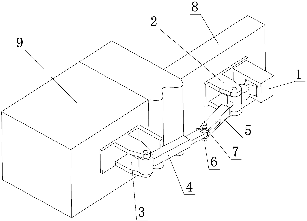
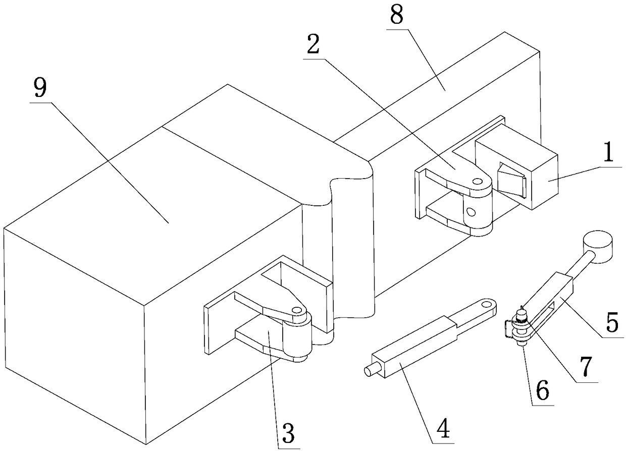
[0020] Such as Figure 1 to Figure 2 Shown, a kind of invisible anti-theft door trigger signal transmitting device, it comprises the signal transmitter 1 that is fixedly installed on the back side of door 8, places the first hinge seat 2 that signal transmitter 1 side is fixedly installed on the back side of door 8, The second hinge base 3 fixedly installed on the wall 9, the drive inner rod 4 that is rotatably connected with the second hinge base 3, and the drive outer rod 5 that is rotatably connected with the first hinge base 2, and the drive inner rod 4 passes through the pin The shaft 6 is rotatably connected to the driving outer rod 5 , and a torsion spring 7 is installed on the pin shaft 6 , and the torsion spring 7 elastically presses between the driving inner rod 4 and the driving outer rod 5 . The signal transmitter 1 is a prior art,...


PUM


Abstract

The invention provides an invisible security door trigger signal emitting device which comprises a signal emitter (1) fixedly arranged on the back surface of a door, a first hinge seat (2) arranged onthe side of the signal emitter (1) and fixedly arranged on the back surface of the door, a second hinge seat (3) fixedly arranged on a wall body, a drive inner rod (4) rotatably connected with the second hinge seat (3); and a drive outer rod (5) rotatably connected with the first hinge seat (2). The drive inner rod (4) is rotatably connected with the drive outer rod (5) through a pin shaft (6); and a torsional spring (7) is further arranged on the pin shaft (6) and is elastically pressed between the drive inner rod (4) and the drive outer rod (5). The invisible security door trigger signal emitting device provided by the invention is simple in structure, low in cost, and convenient and flexible to install, and can be hidden in the door so as not to be damaged artificially.

Description

technical field [0001] The invention relates to the field of anti-theft door anti-theft technology, in particular to a trigger signal transmitting device for an invisible anti-theft door. Background technique [0002] Most of the existing anti-theft alarm devices adopt cameras or infrared alarms, and the existing anti-theft devices are all exposed outdoors, which are easily destroyed by human beings and lose the effect of the anti-theft alarm. [0003] In view of this, the present invention is proposed to solve the deficiencies of the prior art. Contents of the invention [0004] Aiming at the above-mentioned prior art, the technical problem to be solved by the present invention is to provide an invisible anti-theft door trigger signal transmitter device which is simple in structure, low in cost, convenient and flexible in installation, and hidden in the door without artificial damage. [0005] In order to solve the above technical problems, the present invention provides...

Claims


Application Information

Patent Timeline
Patent Type & Authority Applications(China)
IPC IPC(8): E05D3/06E05D11/00G08B13/08
CPCG08B13/08E05D3/06E05D11/00
Inventor 罗柏文胡璇宇
Owner HUNAN UNIV OF SCI & TECH
Why Eureka
Try Eureka