Campus multifunctional solar street lamp
A solar street lamp, multi-functional technology, applied in the field of multi-functional solar street lamps on campus, can solve the problems of inconvenient replacement and maintenance operations, achieve the effects of increasing mechanical strength, stability and safety, realizing rational utilization of resources, and beautiful overall structure
- Summary
- Abstract
- Description
- Claims
- Application Information
AI Technical Summary
Problems solved by technology
Method used
Image
Examples
Embodiment 1
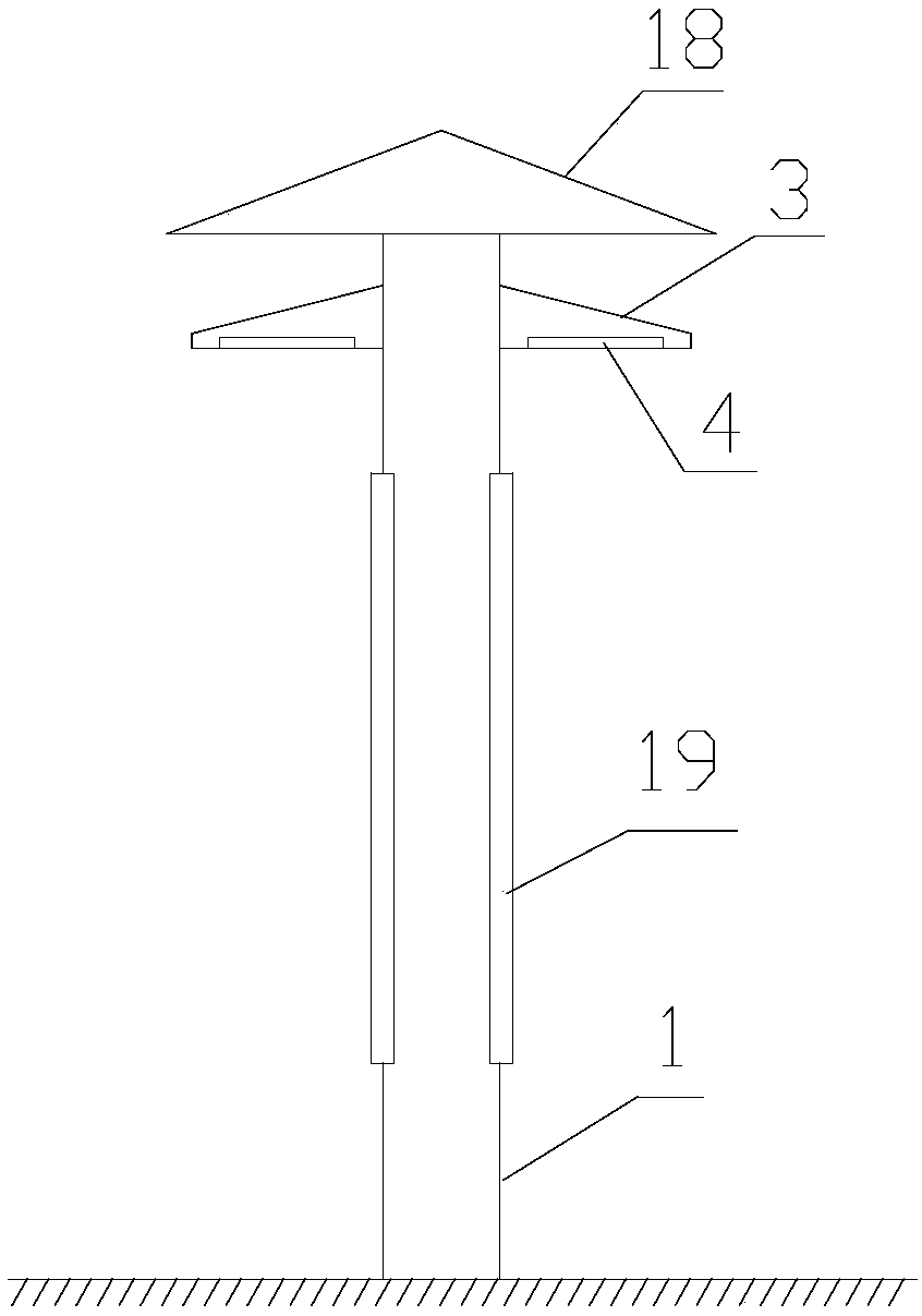
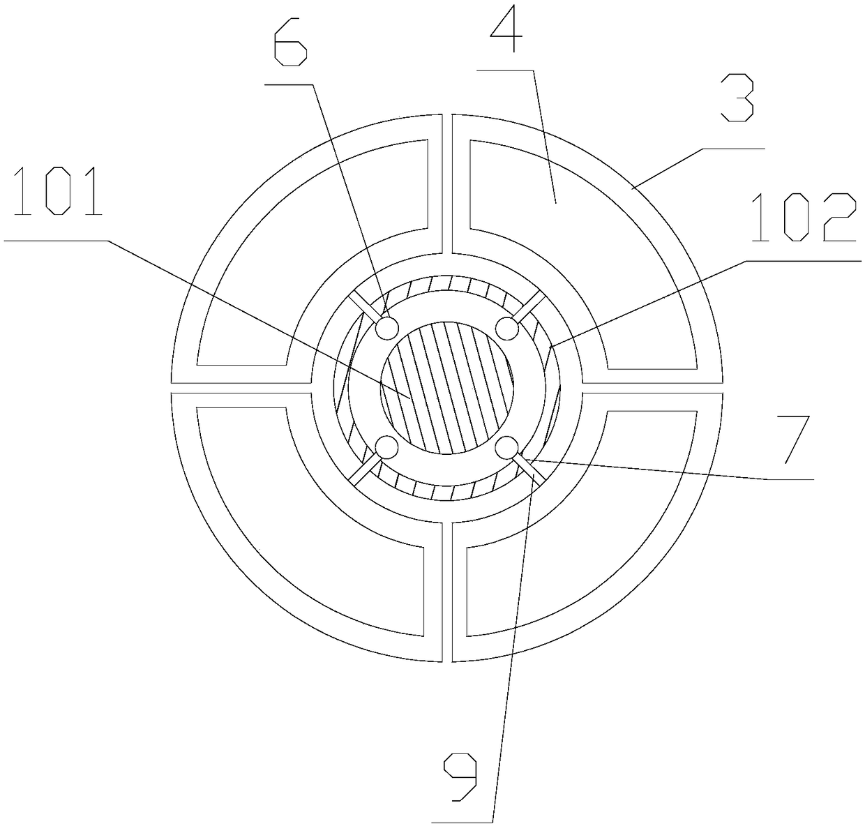
[0042] The present invention provides a campus multifunctional solar street light, which includes a cylinder 1, the axial bottom end of the cylinder 1 is fixed on the ground, and a solar panel 2 is arranged on the top of the cylinder 1, and it is characterized in that the cylinder 1 On the side wall close to the top, there are several fan-shaped mounting plates 3 distributed along the circumferential direction, and several mounting plates 3 are sleeved on the cylinder 1 in a ring structure as a whole, and each mounting plate 3 is installed along the axial direction of the cylinder 1 through the lifting mechanism. Independently move up and down, the lower surface of the mounting plate 3 is provided with a mounting groove, and the LED panel lights 4 are embedded in the mounting grooves, and the LED panel lights 4 on several mounting plates 3 are powered by a parallel circuit; The solar panel 2 is used to provide power for the LED panel light 4 and the lifting mechanism.
Embodiment 2
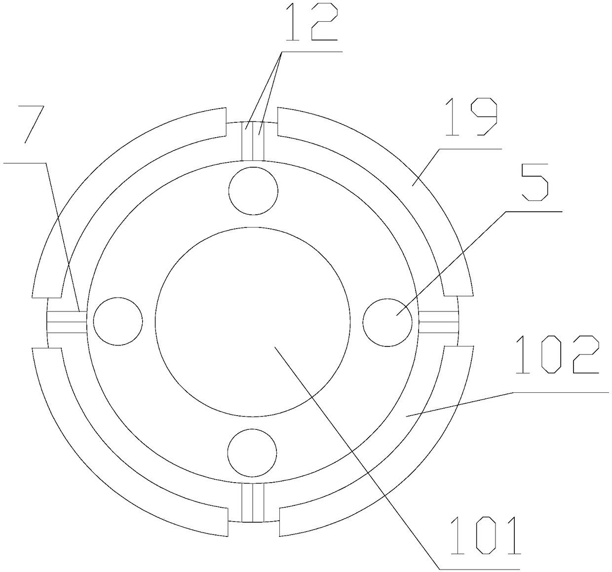
[0044] Further improvement on the basis of Embodiment 1, the lifting mechanism includes a number of screw rods 5 that are adapted to the mounting plate 3 in number and position, and the screw rods 5 are sleeved with drive nuts 6 that are threaded and rotatably connected; The column body 1 includes a fixed column 101 and a mounting sleeve 102 arranged on the coaxial center line. The mounting sleeve 102 is sleeved outside the fixed column 101. The side wall of the mounting sleeve 102 is provided with a number of chute 7, a number of chute 7 Evenly distributed along the circumference of the installation sleeve 102, the extension direction of each chute 7 is parallel to the axial direction of the installation sleeve 102; evenly distributed in the annular cavity between the outer wall of the fixing column 101 and the inner wall of the installation sleeve 102 A screw mandrel 5 is provided, the axial direction of the screw mandrel 5 is parallel to the axial direction of the installati...
Embodiment 3
[0046] Further improvement on the basis of Embodiment 2, the axial bottom end of the fixed column 101 is provided with a first base 103, and the top end is provided with a second base 104, the outer diameter of the second base 104 is smaller than that of the first base The outer diameter of 103; the upper surface of the first base 103 is provided with several mounting holes, and the motor 8 is located in the mounting holes, and the axial bottom end of the screw mandrel 5 is driven by the motor 8 to rotate; the outer side of the second base 104 There are several mounting grooves evenly distributed along the circumference on the wall, and the top of the screw mandrel 5 is rotated and fixed in the mounting grooves through the bearing 10; the bottom side wall of the mounting sleeve 102 is provided with a through hole, and the first base 3 is provided with a threaded hole on the side wall, and screwed into the threaded hole after passing through the through hole through the counters...
PUM
 Abstract
Description
Claims
Application Information
 - R&D
- Intellectual Property
- Life Sciences
- Materials
- Tech Scout
- Unparalleled Data Quality
- Higher Quality Content
- 60% Fewer Hallucinations
Browse by: Latest US Patents, China's latest patents, Technical Efficacy Thesaurus, Application Domain, Technology Topic, Popular Technical Reports.
© 2025 PatSnap. All rights reserved.Legal|Privacy policy|Modern Slavery Act Transparency Statement|Sitemap|About US| Contact US: help@patsnap.com


