A Laminar Flow Header Cooling Water Quantity Control Device

A cooling water volume and control device technology, which is applied to workpiece cooling devices, manufacturing tools, metal rolling, etc., can solve the problems of difficult control of cooling water volume, high equipment manufacturing and operating costs, and improve maintainability, operability, and manufacturing operating costs. Low, the effect of improving work efficiency

Active Publication Date: 2019-12-17
SHANGHAI MEISHAN IRON & STEEL CO LTD
View PDF13 Cites 0 Cited by
  • Summary
  • Abstract
  • Description
  • Claims
  • Application Information

AI Technical Summary

Problems solved by technology

[0006] The object of the present invention is to provide a laminar flow header cooling water volume control device, which mainly solves the technical problems of difficulty in controlling the cooling water volume and high equipment manufacturing and operating costs of the existing hot rolling laminar flow cooling equipment

Method used


Image

  • A Laminar Flow Header Cooling Water Quantity Control Device
  • A Laminar Flow Header Cooling Water Quantity Control Device
  • A Laminar Flow Header Cooling Water Quantity Control Device

Examples


Embodiment 1

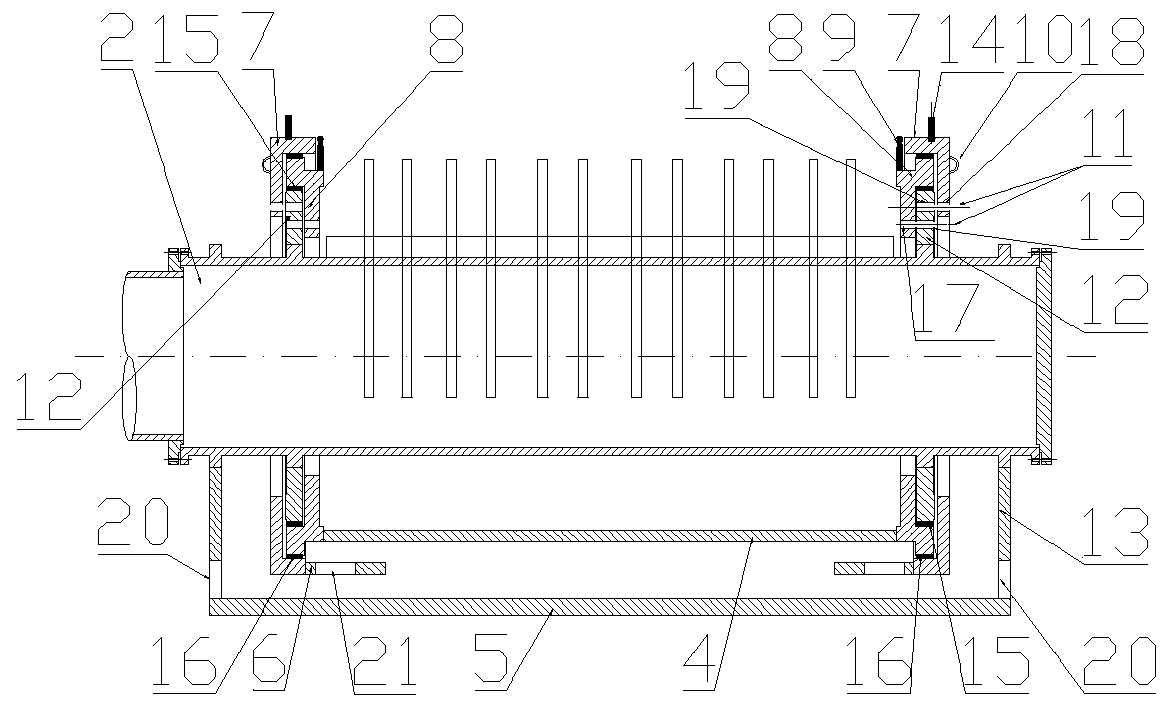
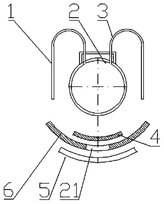
[0034] Embodiment 1, the device of the present invention is used to control the maximum cooling water volume when producing narrow plates, see figure 1 , figure 2 , the header 2 is fixed on the basis of the production line through a bracket, the front outlet pipe 1 and the rear outlet pipe 3 are two rows of headers, which are welded on both sides of the header 2, and the total of the front outlet pipe 1 and the rear outlet pipe 3 The water output is the maximum water output of the rolling line, the water output of the front water outlet pipe 1 is the minimum water output of the rolling line, and the water output of the rear water outlet pipe 3 is between the two. The mounting plate 12 and the header 2 are connected by threads. The inner copper sliding bearing 15 is arranged on the mounting plate 12, so that the flow drive plate 8 can rotate flexibly, and two circles of fixed through holes 19 are arranged on the mounting plate 12, 5 each, so that the fixed pins of the flow dri...

Embodiment 2

[0035] Embodiment 2, the minimum cooling water regulation when the device of the present invention is used to produce narrow plates, see figure 1 , figure 2 , image 3 , adjust the device in Example 1, rotate the flow drive plate 8 through the flow handle 9, make the non-porous arc plate 4 block the rear outlet pipe 3, and align the flow positioning hole 17 with the fixed through hole 19 on the installation plate 12 , Insert the fixed pin 11, the outlet water of the rear outlet pipe 3 is collected by the chute 5, and flows out through the guide hole 20.

Embodiment 3

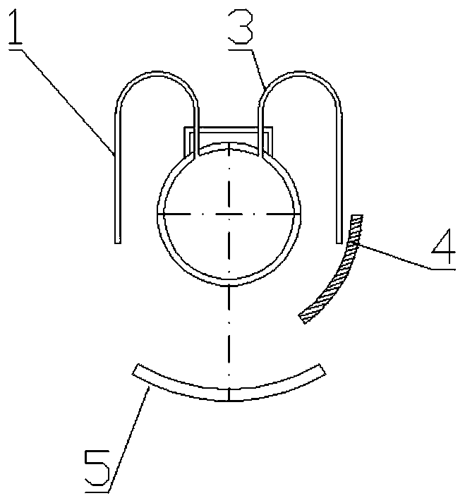
[0036] Embodiment 3, when the device of the present invention is used for medium cooling water regulation when producing narrow plates, see figure 1 , figure 2 , Figure 4 , adjust the device in Example 1, through the flow handle 9, rotate the flow drive plate 8 to block the front outlet pipe 1, and align the flow positioning hole 17 with the fixing through hole 19 on the mounting plate 12, insert the fixing pin 11, The outlet water of the front outlet pipe 1 is collected by the chute 5 and flows out through the diversion hole 20 .


PUM


Abstract

The invention relates to a laminar flow collecting pipe cooling water quantity control device. The control device mainly solves the technical problems that the cooling water amount of existing hot-rolled laminar flow cooling equipment is difficult to regulate and control, and the equipment manufacturing and operation cost is high. The laminar flow collecting pipe cooling water quantity control device comprises a plurality of spraying pipe devices, each spraying pipe device comprises a collecting pipe, a plurality of uniformly distributed spraying pipes, a front water outlet pipe and a rear water outlet pipe are arranged on each collecting pipe, and for each collecting pipe, the front water outlet pipe and the rear water outlet pipe are fixedly arranged on the two sides of the middle of thecollecting pipe correspondingly; and each spraying pipe device further comprises mounting discs, flow driving discs, width driving discs, flow rocking handles, width rocking handles, fixing pins, inner copper sliding bearings, outer copper sliding bearings, pull rings, a hole-free arc-shaped plate, a porous arc-shaped plate and a water sliding groove, wherein the mounting discs are fixedly arranged at the two ends of the collecting pipe, the mounting discs are provided with the inner copper sliding bearings, and two circles of fixing through holes are formed in the surface of each mounting disc. The laminar flow collecting pipe cooling water quantity control device is simple in structure and low in manufacturing and operation cost.

Description

technical field [0001] The invention relates to laminar flow cooling equipment for hot rolling in the field of iron and steel metallurgy, in particular to a laminar flow header cooling water control device, in particular to a laminar flow header for a hot output roller table or a laminar flow roller table of a hot rolling production line Cooling water quantity control device. Background technique [0002] Hot rolling production is a production method for pressure processing of metals at a high temperature of 850-1250°C. However, in the stage of hot output roller table, the amount of cooling water is related to the speed of strip temperature drop and has a great influence on the strength of strip steel. strong relationship. The water demand of the hot run-out roller table is mainly related to the thickness of the strip and the width of the strip. [0003] At present, the header of the heat output roller table generally adopts two methods for spraying water, the laminar flow...

Claims


Application Information

Patent Timeline
Patent Type & Authority Patents(China)
IPC IPC(8): B21B45/02
CPCB21B45/0218Y02P70/10
Inventor 陈高林许士兵袁亚东
Owner SHANGHAI MEISHAN IRON & STEEL CO LTD
Why Eureka
Try Eureka