Floating support device

A floating support and support column technology, applied in positioning devices, supports, clamping and other directions, can solve the problems of unreliable support and clamping of parts and unreliable support of support points, and achieves ingenious structure, accurate support and simple operation. Effect

Pending Publication Date: 2018-11-02
苏州丰川电子科技有限公司
View PDF8 Cites 0 Cited by
  • Summary
  • Abstract
  • Description
  • Claims
  • Application Information

AI Technical Summary

Problems solved by technology

[0002] As we all know, during the machining process of parts, such as the processing of the rear side cover of the notebook computer, the parts need to be supported and positioned by the fixture, but during the processing of the parts, due to the processing error or the height of the supporting surface itself During the clamping process of the existing fixture, there may be a certain support point that cannot be reliably supported, and the reliable support and clamping of the parts cannot be completed.

Method used


Image

  • Floating support device
  • Floating support device
  • Floating support device

Examples


Embodiment 1

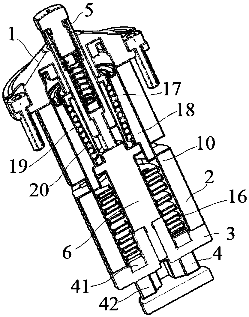
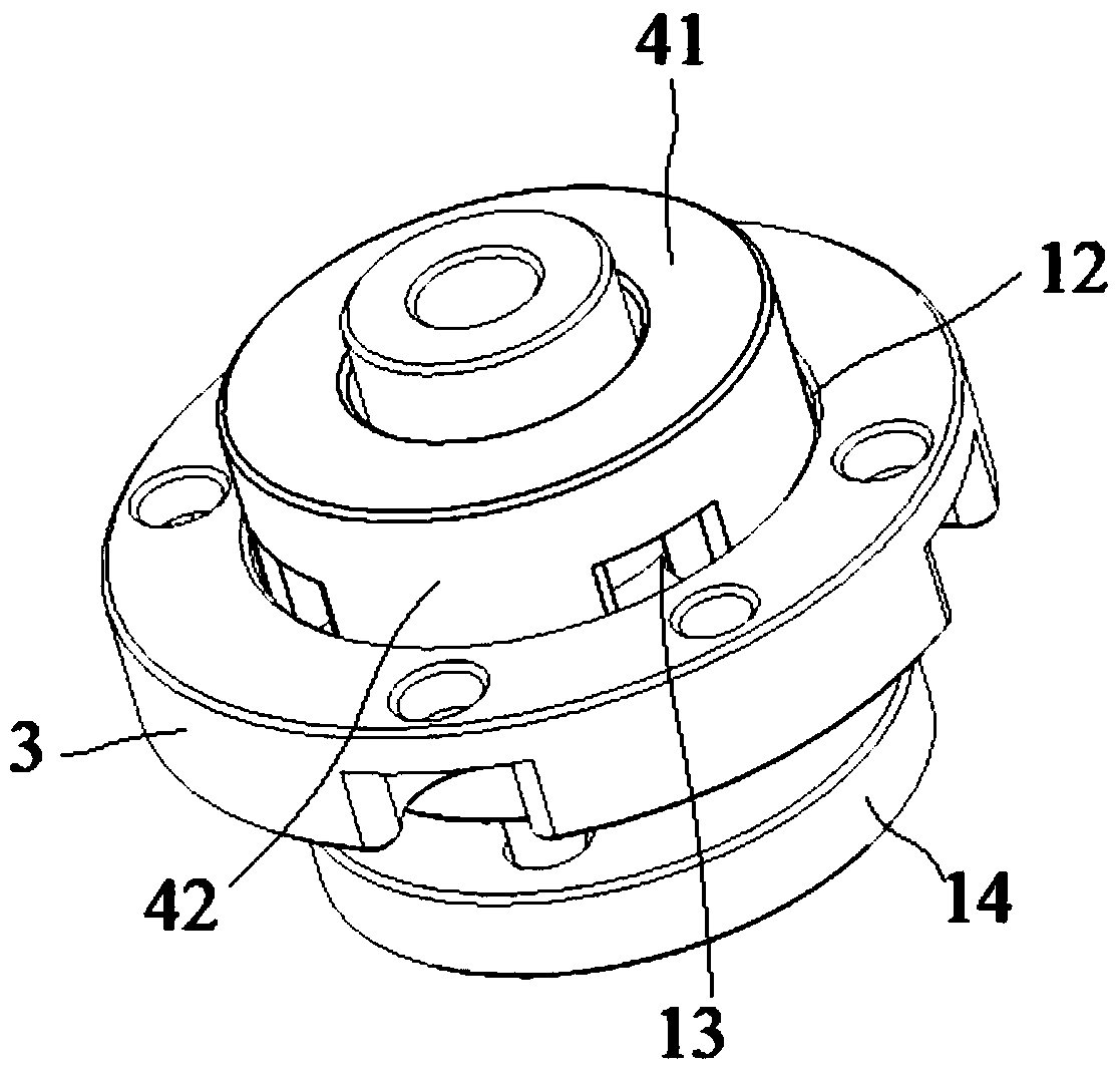
[0030]Embodiment 1: A kind of floating supporting device, comprises top cover 1, housing 2, bottom cover 3, push block 4, movable column 5 and support column 6, described top cover 1 and bottom cover 3 are connected with the shell 2 respectively The top surface and the bottom surface are tightly connected, so that a cavity 10 is formed between the top cover 1, the casing 2 and the bottom cover 3, and the lower end of the movable column 5 passes through the top cover 1 and extends into the cavity 10. The upper end of movable column 5 exposes top cover 1, and described support column 6 is arranged in cavity 10 and the lower end of support column 6 is fixedly connected with bottom cover 3, and described bottom cover 3 upper surface has a groove 12, and this groove The upper surface of 12 is provided with a plurality of through holes 13 for inserting the push block 4. The push block 4 includes a connecting portion 41 and a plurality of protrusions 42. The plurality of protrusions 4...

Embodiment 2

[0037] Embodiment 2: A kind of floating supporting device, comprises top cover 1, shell 2, bottom cover 3, push block 4, movable column 5 and support column 6, described top cover 1 and bottom cover 3 are connected with the shell 2 respectively The top surface and the bottom surface are tightly connected, so that a cavity 10 is formed between the top cover 1, the casing 2 and the bottom cover 3, and the lower end of the movable column 5 passes through the top cover 1 and extends into the cavity 10. The upper end of movable column 5 exposes top cover 1, and described support column 6 is arranged in cavity 10 and the lower end of support column 6 is fixedly connected with bottom cover 3, and described bottom cover 3 upper surface has a groove 12, and this groove The upper surface of 12 is provided with a plurality of through holes 13 for inserting the push block 4. The push block 4 includes a connecting portion 41 and a plurality of protrusions 42. The plurality of protrusions 42...


PUM


Abstract

The invention discloses a floating support device. The device comprises a top cover, a housing, a bottom cover, a push block, a movable column and a support column. The top cover and the bottom coverare connected with the top surface and the bottom surface of the housing in a fastening manner. Therefore, a cavity is formed among the top cover, the housing and the bottom cover. The lower end of the movable column penetrates through the top cover and stretches into the cavity. At this time, the upper end of the movable column is exposed out of the top cover. The support column is arranged in the cavity and the lower end of the support column is fixedly connected with the bottom cover. The upper surface of the bottom cover is equipped with a groove. The lower surface of a baffle board is provided with a groove. Two limiting columns are arranged in parallel and penetrate through a movable sleeve in a horizontal direction. The two limiting rods are located below a second flange of the support column. The upper part of a threaded rod is embedded into the lower part of an outer sleeve and movably connected with the movable sleeve. Through simple structural design, the device can automatically return to the original state. Without adding downward pulling force, all parts can return to the original state. The floating support device is ingenious in structure and convenient to use.

Description

technical field [0001] The invention relates to a floating support device, which belongs to the technical field of precision parts processing of electronic products. Background technique [0002] As we all know, during the machining process of parts, such as the processing of the rear side cover of the notebook computer, the parts need to be supported and positioned by the fixture, but during the processing of the parts, due to the processing error or the height of the supporting surface itself During the clamping process of the existing fixture, there may be a certain support point that cannot be reliably supported, and the reliable support and clamping of the parts cannot be completed. Contents of the invention [0003] The purpose of the present invention is to provide a floating support device, which achieves the effect of automatically returning to the initial state through a simple structural design without adding a downward pulling force to make each component retur...

Claims


Application Information

Patent Timeline
Patent Type & Authority Applications(China)
IPC IPC(8): B23Q3/02
CPCB23Q3/02
Inventor 蒋燕周士升詹淳崵赵长亮
Owner 苏州丰川电子科技有限公司
Why Eureka
Try Eureka