Fire aerial escape passage between community tall buildings

A technology for escape routes and high-rise buildings, which is applied to life-saving equipment, ladders, building rescue, etc., and can solve the problems of not establishing a fire escape route in the air and only enduring the suffering of fireworks

Inactive Publication Date: 2018-11-02
曹伟
View PDF0 Cites 1 Cited by
  • Summary
  • Abstract
  • Description
  • Claims
  • Application Information

AI Technical Summary

Problems solved by technology

[0002] Existing high-rise fire escape channels, one is to escape from the stairs; the other is to rescue the trapped people from the doors and windows through the ladder; the third is to escape to the roof platform to wait for rescue; Escape from below; Invention Patent No. 2016112708937, the patent name is "High-rise Outdoor Rescue Ladder", which is usually fixed on the inner wall of the window sill on each floor of the high-rise building. When a fire occurs, the fixed cloth in the storage box of the cloth ladder The tube ladder is pulled out, and the outlet of the bottom layer of the cloth tube ladder is thrown out of the window sill frame. Inside the cloth tube ladder, there is a soft belt ladder, which can be lowered to the ground step by step through the soft belt ladder. Falling inside the cloth tube ladder, using multiple elastic elastic bands to reduce the diameter of the tube tube ladder in multiple parts, can catch the human body to prevent the fall. This invention patent also adopts the vertical escape method from the window from top to bottom; when people come from When escaping indoors to the top platform of a high building, the flames will spread upward when the high building is on fire. People waiting for rescue on the top platform of the high building can only endure the suffering of fireworks. The adjacent density of high-rise buildings is very high, and the adjacent distance between the surrounding high-rise buildings is very short. In the current high-rise fire rescue facilities, there is no fire escape channel.

Method used


Image

  • Fire aerial escape passage between community tall buildings
  • Fire aerial escape passage between community tall buildings

Examples


Embodiment Construction

[0010] The present invention is further described below in conjunction with embodiment and accompanying drawing.

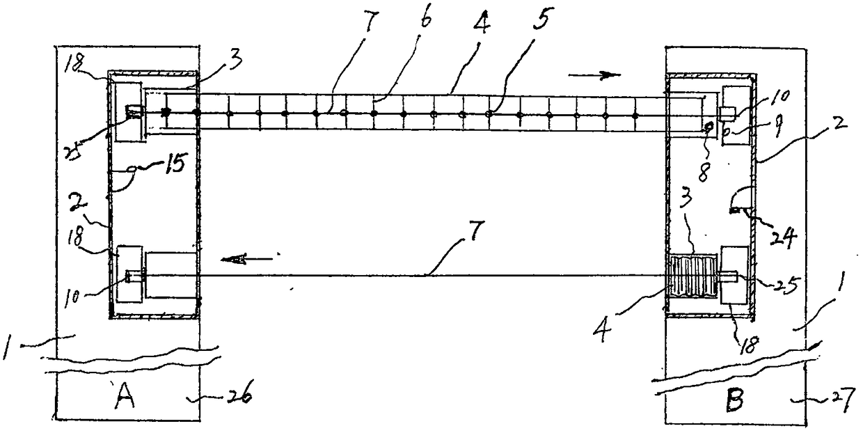
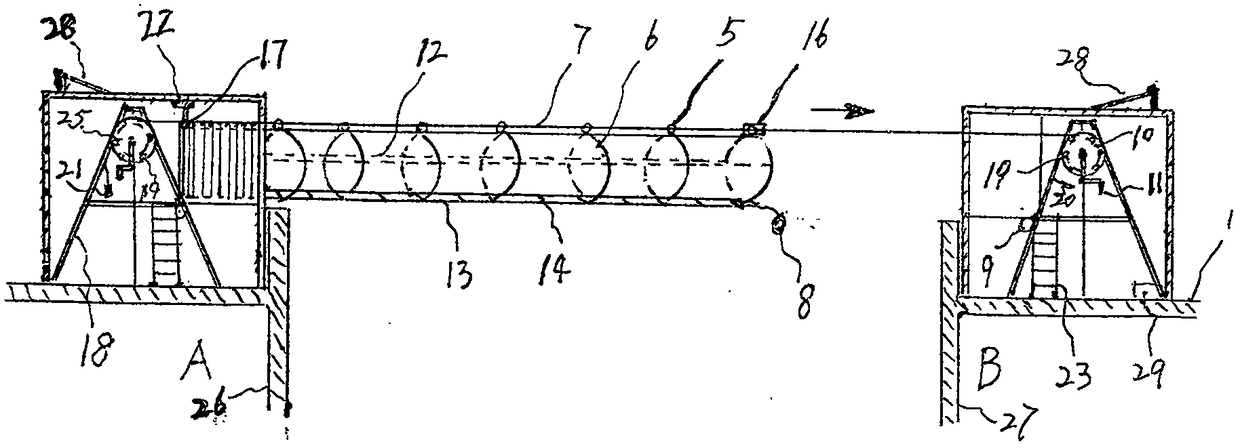
[0011] see figure 1 , on the tall roof platform (1) between A building (26) and B building (27), respectively be provided with a cableway tube ladder room (2), all two steel tube ladder rooms (2) in every cableway tube ladder room (2) The cable support (18) is respectively equipped with a tube ladder traction wheel (10) and a tube ladder return wheel (25), in the air between the two buildings of A building (26) and B building (27), with two steel bars Cable (7), respectively connects the barrel ladder traction wheel (10) and the barrel ladder return wheel (25) in the cableway barrel ladder room (2) on the A building (26) and the B building (27); use the barrel ladder storage box ( 3) The foldable barrel ladder (4) inside is suspended on the steel cable (7), drives the foldable barrel ladder (4) to move forward through the barrel ladder traction wheel (10), and pa...


PUM


Abstract

The invention discloses a fire aerial escape passage between community tall buildings. A cableway barrel ladder room (2) is arranged on each of tall building top platforms (1) between a building A (26) and a building B (27) and is internally provided with two steel cable brackets (18) which are provided with a barrel ladder traction wheel (10) and a barrel ladder return wheel (25) respectively; inthe air between the two buildings, two steel cables (7) are connected with the barrel ladder traction wheels (10) and the barrel ladder return wheels (25) in the cableway barrel ladder rooms (2) respectively; foldable barrel ladders (4) in barrel ladder storage tanks (3) are used to be hung on the steel cables (7) respectively; the barrel ladder traction wheels (10) are rocked to turn to drive the foldable barrel ladders (4) to advance; multiple steel cable rings (5) penetrate through the steel cables (7) respectively and then are connected with barrel arrangement metal rings (6) respectively; the foldable barrel ladders (4) and the barrel arrangement metal rings (6) are sutured and connected to form a closed transverse type soft barrel ladder to establish an aerial escape passage betweenthe two buildings; and a room door alarm (15) is arranged on each barrel ladder room door (24). The passage is simple and reliable to operate, is safe and economic and facilitates community residentsto perform self saving and mutual saving at the first time when a tall building fire occurs to reduce personal injuries or death.

Description

technical field [0001] The invention relates to the field of fire rescue in high-rise buildings, in particular to an aerial escape channel for fires between high-rise buildings in communities. Background technique [0002] Existing high-rise fire escape channels, one is to escape from the stairs; the other is to rescue the trapped people from the doors and windows through the ladder; the third is to escape to the roof platform to wait for rescue; Escape from below; Invention Patent No. 2016112708937, the patent name is "High-rise Outdoor Rescue Ladder", which is usually fixed on the inner wall of the window sill on each floor of the high-rise building. When a fire occurs, the fixed cloth in the storage box of the cloth ladder The tube ladder is pulled out, and the outlet of the bottom layer of the cloth tube ladder is thrown out of the window sill frame. Inside the cloth tube ladder, there is a soft belt ladder, which can be lowered to the ground step by step through the sof...

Claims


Application Information

Patent Timeline
IPC IPC(8): E06C1/56A62B1/00
CPCE06C1/56A62B1/00
Inventor 曹伟
Owner 曹伟
Why Eureka
Try Eureka