
Small switch cabinet valve mechanism

A technology of switch cabinets and valves, which is applied in the direction of pull-out switch cabinets, switch devices, guard plates/protection devices of switch devices, etc. It can solve the problems of straight angle between the rotary plate and the lower valve bracket, unsafe, wide volume, etc. To achieve the effect of increasing the electrical insulation distance

Pending Publication Date: 2018-11-02
上海洪电电气有限公司
View PDF4 Cites 2 Cited by
  • Summary
  • Abstract
  • Description
  • Claims
  • Application Information

AI Technical Summary

Problems solved by technology

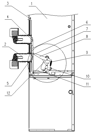
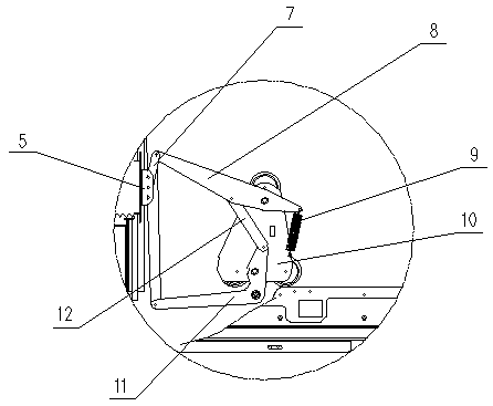
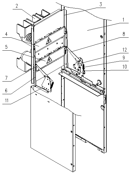
[0002] With the development of society, the area of ​​power distribution room in the field of power supply and distribution is getting smaller and smaller, and more and more miniaturized switchgears are used for electricity. Traditional switchgears such as KYN28 switchgears have a phase-to-phase distance of 210mm and a volume of Larger, miniaturized switchgear such as a removable small switchgear with a width of 550mm, the distance between the phases does not exceed 150mm, the traditional valve mechanism, such as the valve mechanism disclosed in the patent application number: 201720060796.9, and the one disclosed in the patent application number: 201220584506.8 In the valve mechanism of high-voltage switchgear, the upper valve plate and the lower valve plate are respectively connected with the upper and lower arms of the valve working mechanism, and the upper and lower arms work independently, so the volume is relatively wide, and the necessary electrical safety distance cannot be guaranteed. To solve this problem Problem, patent application number 201620569335.X discloses a valve mechanism for electrical cabinets and patent application number: 201610414261.7 discloses an electrical cabinet with a triangular valve mechanism. When the upper valve and the lower valve are opened, a valve passes through the upper part of the upper valve. Rotary plate transfer, when the upper valve is opened, it drives the rotary plate to rotate to push the lower valve to open. However, in this way, there are many rotating points of parts, the length of the rotary plate is too long, the swing range is large, and it is close to the high-voltage charged body, which is not safe. , and the angle between the rotating plate and the lower valve bracket is relatively straight, which is easy to get stuck and cause failure

Method used


Image

  • Small switch cabinet valve mechanism
  • Small switch cabinet valve mechanism
  • Small switch cabinet valve mechanism

Examples


Embodiment Construction

[0018] It should be noted that, in the case of no conflict, the embodiments of the present invention and the features in the embodiments can be combined with each other.

[0019] In describing the present invention, it should be understood that the terms "center", "longitudinal", "transverse", "upper", "lower", "front", "rear", "left", "right", " The orientations or positional relationships indicated by "vertical", "horizontal", "top", "bottom", "inner" and "outer" are based on the orientations or positional relationships shown in the drawings, and are only for the convenience of describing the present invention and Simplified descriptions, rather than indicating or implying that the device or element referred to must have a particular orientation, be constructed and operate in a particular orientation, and thus should not be construed as limiting the invention.

[0020] In the description of the present invention, it should be noted that unless otherwise specified and limited...


PUM


Abstract

The invention relates to a small switch cabinet valve mechanism which comprises a cabinet body, two groups of contact boxes up and down, two guide rods, an upper valve, a lower valve, upper connectingplates, lower connecting plates, upper pushing plates, tension springs, support plates, lower pushing plates and adapter arms; the cabinet body comprises a left side plate, a right side plate and a middle partition plate; the upper valve and the lower valve are mounted on the two guide rods, and can slide up and down; the upper connecting plates, the lower connecting plates, the upper pushing plates, the tension springs, the support plates, the lower pushing plates and connecting arms are all arranged in pairs, and are symmetrically arranged on the two sides; a matched handcart enters to pushthe lower pushing plates to rotate, and the lower pushing plates sequentially drive the upper connecting plates, the upper pushing plates, the lower connecting plates and the upper valve and the lower valve to move, so that the upper valve and the lower valve can be far away from the contact boxes; after the matched handcart is in place, a movable contact is combined with a static contact in eachcontact box to form a conductive loop; and after the matched handcart is driven out, the upper valve and the lower valve are automatically closed.

Description

technical field [0001] The invention relates to the technical field of machinery, in particular to an electric cabinet valve mechanism. Background technique [0002] With the development of society, the area of ​​power distribution room in the field of power supply and distribution is getting smaller and smaller, and more and more miniaturized switchgears are used for electricity. Traditional switchgears such as KYN28 switchgears have a phase-to-phase distance of 210mm and a volume of Larger, miniaturized switchgear such as a removable small switchgear with a width of 550mm, the distance between phases does not exceed 150mm, the traditional valve mechanism, such as the valve mechanism disclosed in the patent application number: 201720060796.9, and the one disclosed in the patent application number: 201220584506.8 In the valve mechanism of high-voltage switchgear, the upper and lower valve plates are respectively connected to the upper and lower arms of the valve working mech...

Claims


Application Information

Patent Timeline
Patent Type & Authority Applications(China)
IPC IPC(8): H02B11/24H02B11/167
CPCH02B11/167H02B11/24
Inventor 梁作鹏孙成杰
Owner 上海洪电电气有限公司
Learn More