
Solid Insulated Disconnect Switch

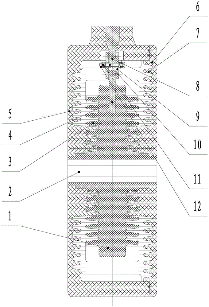
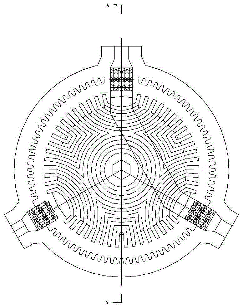
A technology of isolating switch and solid insulation, applied in the direction of air switch components, etc., can solve the problem of electrical insulation distance limitation, and achieve the effect of increasing the electrical insulation distance

Active Publication Date: 2016-07-27
BEIJING SOJO ELECTRIC
View PDF7 Cites 0 Cited by
  • Summary
  • Abstract
  • Description
  • Claims
  • Application Information

AI Technical Summary

Problems solved by technology

[0004] The main purpose of the present invention is to provide a solid insulation isolating switch to solve the problem that the electrical insulation distance is limited

Method used


Image

  • Solid Insulated Disconnect Switch
  • Solid Insulated Disconnect Switch

Examples


Embodiment Construction

[0019] It should be noted that, in the case of no conflict, the embodiments in the present application and the features in the embodiments can be combined with each other. The present invention will be described in detail below with reference to the accompanying drawings and examples.

[0020] It should be noted that the terms "first" and "second" in the description and claims of the present invention and the above drawings are used to distinguish similar objects, but not necessarily used to describe a specific sequence or sequence. It is to be understood that the data so used are interchangeable under appropriate circumstances such that the embodiments of the invention described herein can be practiced in sequences other than those illustrated or described herein. Furthermore, the terms "comprising" and "having", as well as any variations thereof, are intended to cover a non-exclusive inclusion.

[0021] figure 1 is a schematic structural diagram of a solid insulated isolat...


PUM


Abstract

The invention discloses a solid insulation isolating switch. The solid insulating isolating switch is a cylinder, and a first umbrella group is injection molded around the solid insulating isolating switch. The invention solves the problem that the electrical insulation distance is limited, and further achieves the effect of increasing the electrical insulation distance.

Description

technical field [0001] The invention relates to the field of switches, in particular to a solid insulation isolating switch. Background technique [0002] The traditional solid insulated isolating switch includes isolating blades, static contacts, which are installed inside the solid insulating device with vacuum tubes, and at the same time, the upper or lower part of the solid insulated device is equipped with incoming or outgoing bushings to connect with the busbar or cable, so Only a single incoming line grounding or outgoing line grounding can be realized. The closing and grounding operations of the main circuit are realized through the opening and closing of the isolating knife. Due to the limited space of the internal parts of the insulating device body, the electrical insulation distance is limited. This method undoubtedly increases the volume of the solid insulating device body, and at the same time increases the difficulty of installation, and is inconvenient to op...

Claims


Application Information

Patent Timeline
Patent Type & Authority Patents(China)
IPC IPC(8): H01H31/02
Inventor 唐晓鹏宫立超韩雪莲李宗旺孙龙周彦昭
Owner BEIJING SOJO ELECTRIC
Learn More