Eureka AIR delivers breakthrough ideas for toughest innovation challenges, trusted by R&D personnel around the world.

Connector

a technology of connecting rods and connectors, applied in the direction of couplings/cases, coupling device connections, electrical devices, etc., can solve the problems of curtailing interference between, lengthening the insulating distance in the direction, etc., to curtailing any increase in the size of the connector, and lengthening the insulating distance from the conductive member

Inactive Publication Date: 2017-07-11
MOLEX INC
View PDF22 Cites 4 Cited by
  • Summary
  • Abstract
  • Description
  • Claims
  • Application Information

AI Technical Summary

Benefits of technology

[0005]It is an object of the Present Disclosure to provide a connector in which the insulating distance from the conductive member to the outer surface of the housing can be lengthened while curtailing any increase in the size of a connector.
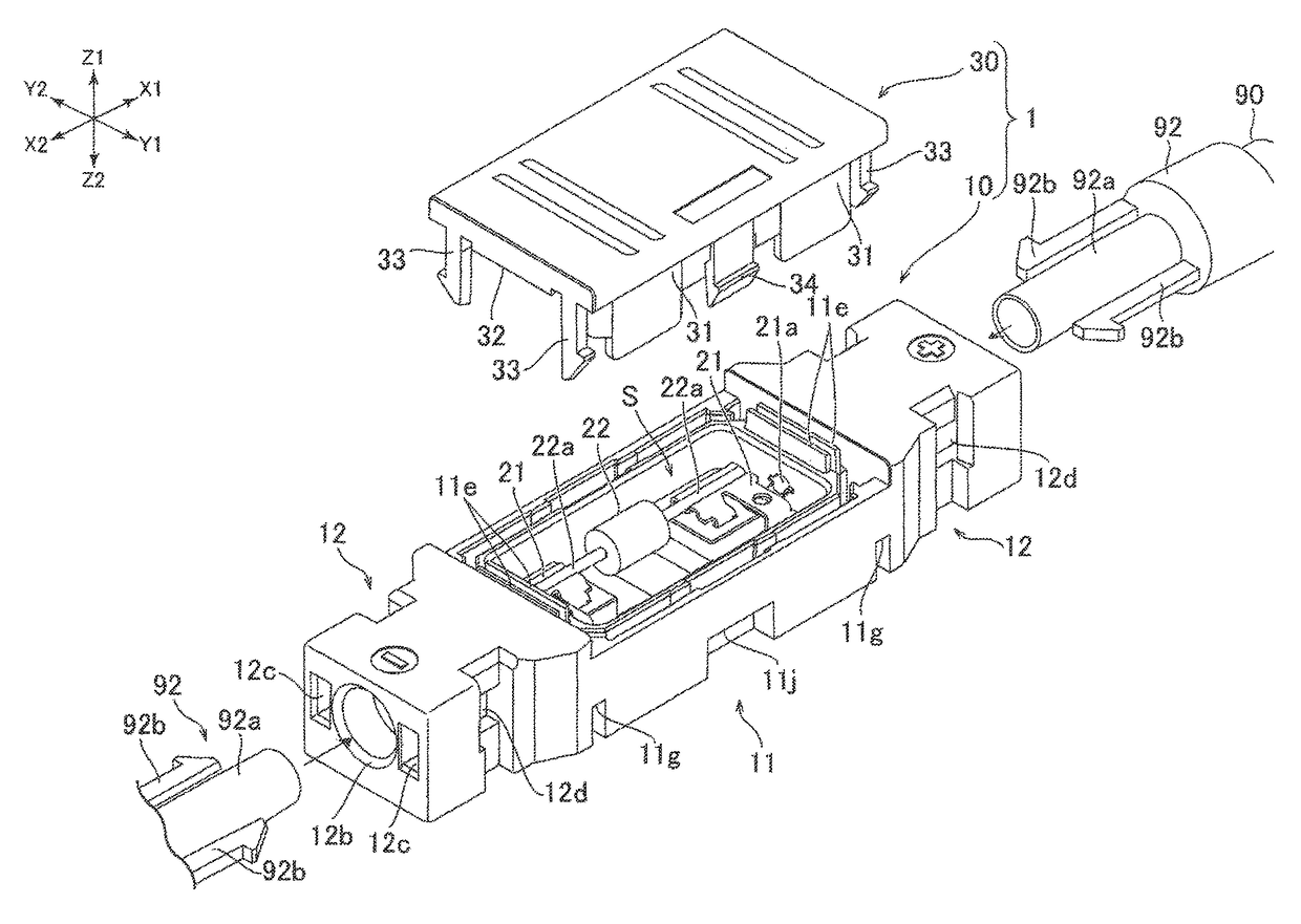
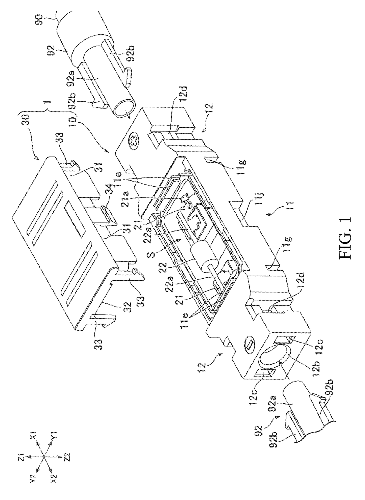
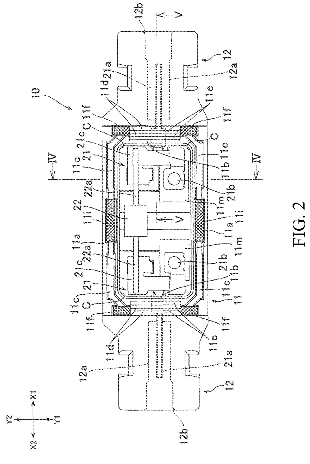
[0006]Accordingly, the Present Disclosure is a connector including a housing having a housing chamber open in a first direction and an opening formed in a second direction orthogonal to the first direction for insertion of another connector provided at the end of a cable. Conductive members housed inside the housing chamber and connected to terminals on the other connector. A cover mounted on the housing in the first direction for closing the housing chamber. A plurality of ribs formed on one of either the cover or the housing, protruding in the other direction, and surrounding the outer periphery of the housing chamber. A plurality of grooves formed on the other of either the cover or the housing for receiving the plurality of ribs. The plurality of ribs include a first rib positioned with respect to the housing chamber in a third direction orthogonal to both the first direction and the second direction, and a second rib positioned on the opening side with respect to the housing chamber. This connector is able to lengthen the insulating distance from the conductive member to the outer surface of the housing while curtailing any increase in the size of a connector.
[0007]In the connector of the Present Disclosure, the protruding length of the second rib may be smaller than the first rib. This can curtail interference between the second rib and the conductive member or the terminals of the other connector, and lengthen the insulating distance in the direction from the conductive member to the opening for receiving the inserted connector. The plurality of ribs may include a plurality of second ribs positioned on the opening side with respect to the housing chamber. This can lengthen the insulating distance in the direction from the conductive member to the opening for receiving the inserted connector.
[0008]In the connector of the Present Disclosure, the housing has two openings positioned on opposite ends from each other in the second direction for receiving two other inserted connectors, the plurality of ribs including two first ribs positioned on opposite sides of the housing chamber from each other in the third direction, and two second ribs positioned on opposite sides of the housing chamber from each other in the second direction. This can lengthen the insulating distance in a connector receiving two other inserted connector.
[0009]In the connector of the Present Disclosure, a hook is formed on one of either the cover or the housing to hook the other one. The hook surrounds the plurality of ribs and the housing chamber, and is connected to the first rib. Because the first rib is connected to the hook, the insulating performance of the connector can be improved.
[0010]The connector of the Present Disclosure may also include a ring-shaped sealing member for sealing the space between the cover and the housing, and the sealing member may be arranged to the inside of the plurality of ribs. This can seal the space between the cover and the housing while curtailing any increase in the size of the connector.

Problems solved by technology

This can curtail interference between the second rib and the conductive member or the terminals of the other connector, and lengthen the insulating distance in the direction from the conductive member to the opening for receiving the inserted connector.

Method used


Image

  • Connector
  • Connector
  • Connector

Examples


Embodiment Construction

[0017]While the Present Disclosure may be susceptible to embodiment in different forms, there is shown in the Figures, and will be described herein in detail, specific embodiments, with the understanding that the Present Disclosure is to be considered an exemplification of the principles of the Present Disclosure, and is not intended to limit the Present Disclosure to that as illustrated.

[0018]As such, references to a feature or aspect are intended to describe a feature or aspect of an example of the Present Disclosure, not to imply that every embodiment thereof must have the described feature or aspect. Furthermore, it should be noted that the description illustrates a number of features. While certain features have been combined together to illustrate potential system designs, those features may also be used in other combinations not expressly disclosed. Thus, the depicted combinations are not intended to be limiting, unless otherwise noted.

[0019]In the embodiments illustrated in ...


PUM


Abstract

To lengthen the insulating distance from a conductive member to the outer surface of a housing while curtailing any increase in the size of a connector, a plurality of ribs are formed on a cover which protrude towards a housing and surround the outer periphery of a housing chamber in the housing. Grooves are formed in the housing for insertion of the ribs. The plurality of ribs provided in the cover include a first rib positioned in the longitudinal direction relative to the housing chamber, and a second rib positioned on the side of the housing chamber with an opening for insertion of another connector.

Description

CROSS REFERENCE TO RELATED APPLICATIONS[0001]The Present Disclosure claims priority to prior-filed Japanese Patent Application No. 2013-082481, entitled “Connector,” filed on 10 Apr. 2013 with the Japanese Patent Office. The content of the aforementioned Patent Application is fully incorporated in its entirety herein.BACKGROUND OF THE PRESENT DISCLOSURE[0002]The Present Disclosure relates, generally, to connectors mounted on a plurality of photovoltaic panels and connected to each other via a cable.[0003]Photovoltaic systems usually include a plurality of photovoltaic panels. These photovoltaic panels are typically arranged in vertical and / or lateral rows and connected to each other via cables. A connector for connecting the cable is mounted on each panel. A connector used for this purpose has been disclosed in Japanese Utility Model Patent No. 3069523, the content of which is hereby incorporated herein in its entirety. This connector has a housing (a box housing main body) for hous...

Claims


Application Information

Patent Timeline
Patent Type & Authority Patents(United States)
IPC IPC(8): H01R4/22H01R13/502H01R13/52H02G3/16H02S40/34H02G3/08H02G3/06
CPCH02G3/16H02S40/34H01R13/502H01R13/5202H01R13/5213H02G3/088H02G3/0616Y02E10/50
Inventor YAMADA, EIICHICHIKANO, KOJI
Owner MOLEX INC
Why Eureka
Eureka Blog
Learn More