Electromagnetic relay with injection molded yoke

An electromagnetic relay and yoke technology, applied in electromagnetic relays, electromagnetic relay details, relays, etc., can solve problems such as insufficient insulation creepage distance, broken enameled wires, and difficult assembly, and achieve improved dimensional consistency and increased size. Insulation distance, the effect of reducing the assembly process

Active Publication Date: 2016-12-07
XIAMEN HONGFA SIGNAL ELECTRONICS CO LTD
View PDF5 Cites 4 Cited by
  • Summary
  • Abstract
  • Description
  • Claims
  • Application Information

AI Technical Summary

Problems solved by technology

This kind of electromagnetic relay mainly has the following disadvantages: the insulation (ie creepage distance) between the yoke iron and the coil (ie enameled wire) is not enough
[0003] In order to solve the above-mentioned problems, the method adopted in the prior art is to wrap a whole circle of adhesive tape on the coil (ie, enameled wire) to increase the degree of insulation between the coil (ie, enameled wire) and the yoke. The surface of the coil enameled wire is treated with tape, on the one hand, it will increase a process, on the other hand, there is a risk of breaking the enameled wire; the other is to put insulating tape or plastic sheet between the coil and the yoke, figure 2 A schematic diagram of the structure of an existing electromagnetic relay loaded with insulating tape or plastic sheet, such as figure 2 As shown, a plastic sheet 105 is installed between the yoke 102 and the coil 103, thereby improving the degree of insulation between the coil (that is, enameled wire) and the yoke, but this kind of insulation tape is inserted between the coil and the yoke Or the way of plastic sheets, one is to add a process, and the other is that the assembly is difficult, and the position of the insulating tape and the plastic sheet is relatively large (that is, the insulating glue has low precision when winding and it is difficult to completely wrap the enameled wire, or plastic The film is not completely fixed, it is easy to shake during use or transportation), it is difficult to ensure the consistency of the insulation effect, and the third is to reserve assembly space, which will affect the winding space of the enameled wire, which is not conducive to improving the performance of the product

Method used


Image

  • Electromagnetic relay with injection molded yoke
  • Electromagnetic relay with injection molded yoke
  • Electromagnetic relay with injection molded yoke

Examples


Embodiment 1

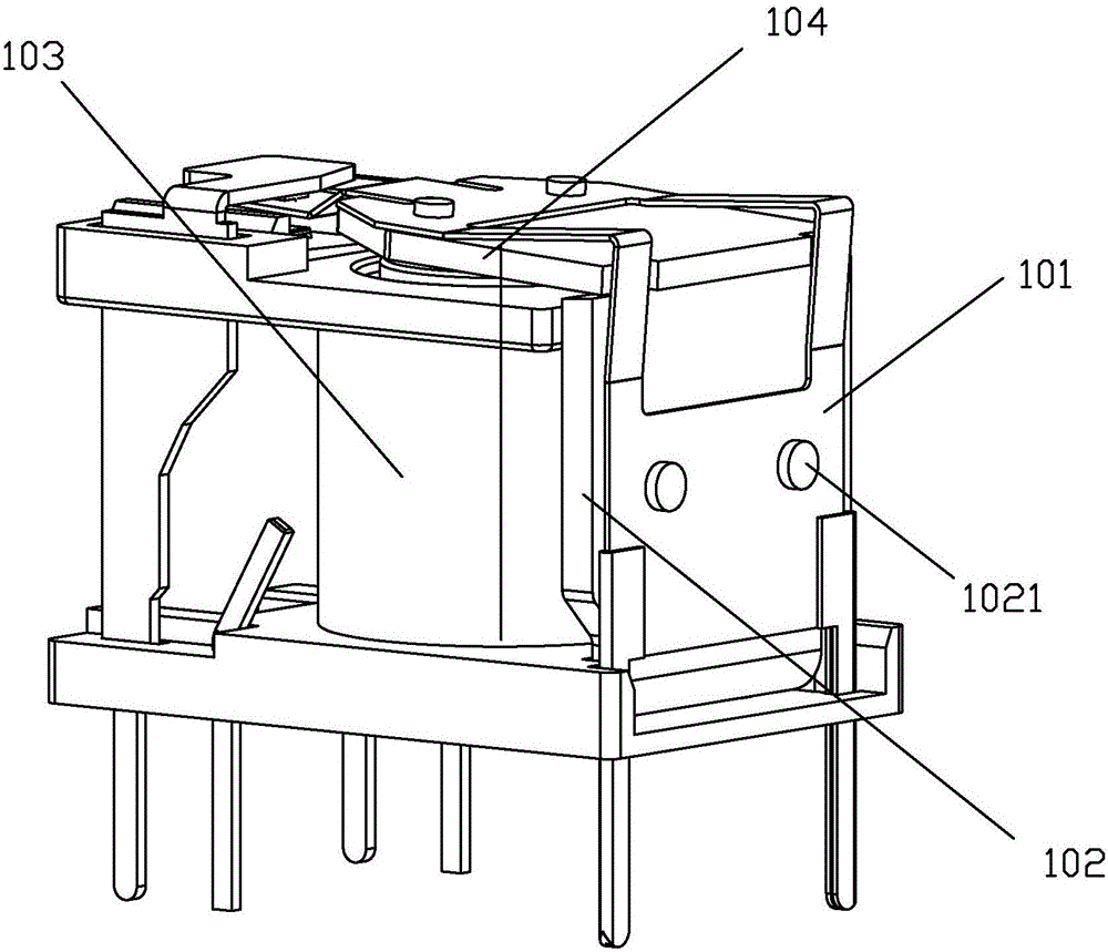
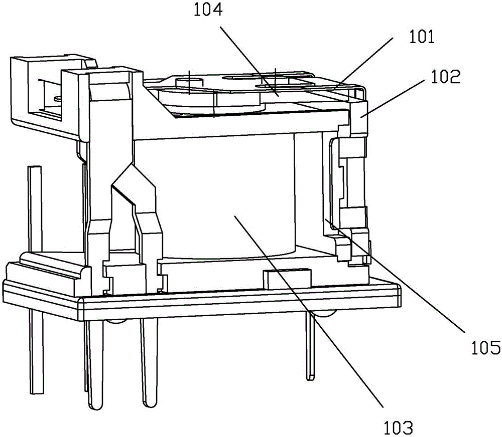
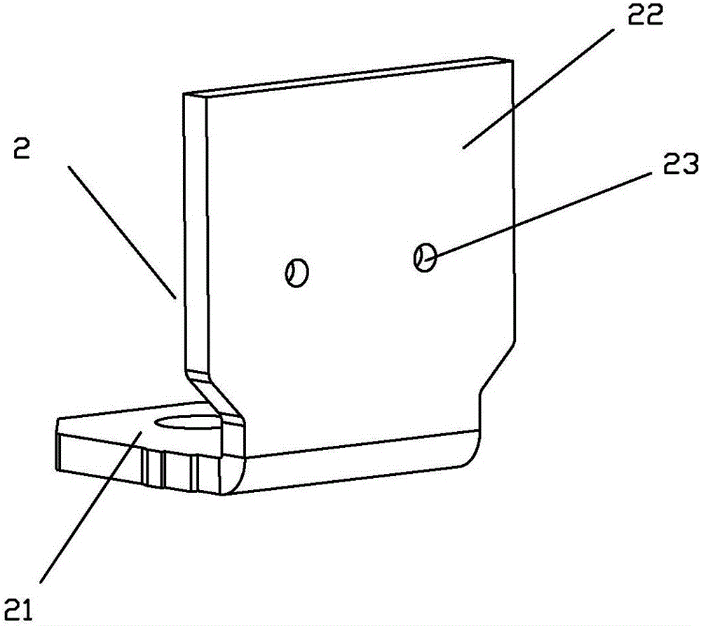
[0044] see Figure 3 to Figure 10 As shown, an electromagnetic relay of an injection molded yoke of the present invention includes a moving spring 1, a yoke 2 and a coil 3, wherein the yoke 2 is L-shaped, and the moving spring 1 and the armature 4 are assembled together to form a moving spring armature assembly The horizontal one side 21 of the yoke iron and the iron core in the coil 3 are fixed at the bottom of the coil 3 (the iron core is contained in the through hole of the coil frame 5 of the coil 3, and the through hole of the coil frame 5 is vertically arranged), The vertical side 22 of the yoke 2 is parallel to the axis of the iron core; in the vertical side 22 of the yoke 2, a plastic layer 61 formed by injection molding is provided on the side facing the coil 3, so as to use the plastic layer 61 to insulate It is arranged between the yoke 2 and the coil 3 (that is, the enameled wire of the coil), and on the side facing away from the coil 3, there is a plastic convex b...

Embodiment 2

[0062] see Figure 11 to Figure 13 As shown, the electromagnetic relay of an injection molded yoke in the present invention differs from the first embodiment in that the moving spring and the yoke are fixed in a different way. In this embodiment, the moving spring 1 and the yoke 2 are fixed It is to insert the plastic convex bud 62 formed on the yoke into the second through hole 11 of the moving spring 1. At this time, the second through hole 11 of the moving spring 1 plays a positioning role, because the through hole can be connected with the yoke. The convex bud 62 formed by the first through hole 23 of the moving spring 1 forms a clearance fit, and then, by hot riveting the plastic convex bud protruding outside the second through hole 11 of the moving spring 1, the plastic convex bud of this part is deformed 621 and All or part of the moving spring body other than the second through hole 11 of the moving spring 1 is covered to realize the fixing of the moving spring 1 and t...


PUM


Abstract

The invention discloses an electromagnetic relay with an injection molded yoke. The electromagnetic relay comprises a movable spring, the yoke and a coil. The yoke is in an L shape, the horizontal side of the yoke and an iron core in the coil are fixed at the bottom of the coil, and the vertical side of the yoke is parallel to the axis of the iron core. In the vertical side of the yoke, a plastic layer is formed on the face facing the coil in an injection molding mode and is used for being arranged between the yoke and the coil in an insulation mode, a plastic protruding bud is formed on the face opposite to the coil in an injection molding mode, and the yoke and the movable spring are fixed through the plastic protruding bud. By means of the electromagnetic relay, on one hand, on the premise that the winding space is not influenced, the insulation degree of the yoke and the coil can be improved, the position precision of an insulation component can be ensured, and assembling procedures are effectively reduced; on the other hand, when the yoke and the movable spring are fixed, it can be avoided that the movable spring is deformed due to stress generated on the movable spring, and the size uniformity of the movable spring is improved.

Description

technical field [0001] The invention relates to the technical field of relays, in particular to an electromagnetic relay of an injection molded yoke. Background technique [0002] figure 1 It is a structural diagram of an existing electromagnetic relay, which is also a classic structure widely used in the relay industry. This electromagnetic relay includes a moving spring 101, a yoke 102 and a coil 103, wherein the yoke 102 is L-shaped, and the yoke 102 is One side of the horizontal side is fixed with the iron core in the coil 103 at the bottom of the coil, and the vertical side of the yoke 102 is parallel to the axis of the iron core. The moving spring 101 and the armature 104 are packed together to form a moving spring armature assembly. There is a convex bud 1021, and the moving spring 101 is provided with an opening. Through the cooperation of the opening of the moving spring 101 and the convex bud 1021 of the yoke 102 and the use of pressure riveting, the moving spring...

Claims


Application Information

Patent Timeline
Patent Type & Authority Applications(China)
IPC IPC(8): H01H50/36
CPCH01H50/36H01H2050/446H01H50/042H01H50/023H01H11/00H01H50/18H01H50/44
Inventor 林佳宾郭齐岳汪志坤
Owner XIAMEN HONGFA SIGNAL ELECTRONICS CO LTD
Why Eureka
Try Eureka