Ignition coil

a technology of ignition coil and coil body, which is applied in the direction of transformer/inductance details, inductance, electrical equipment, etc., can solve the problems of reducing the life of the dielectric breakdown, further degradation of the plastic member, and shortened dielectric breakdown life, so as to reduce the formation of an air layer promoting the dielectric breakdown, reduce the insulation distance between the secondary coil and the outer periphery core, and effectively restrict the effect of dielectric breakdown

Active Publication Date: 2009-01-08
DENSO CORP
View PDF7 Cites 4 Cited by
  • Summary
  • Abstract
  • Description
  • Claims
  • Application Information

AI Technical Summary

Benefits of technology

[0018]For example, the stress relaxation member is a heat shrinkable tube and covers an entire area of the opposing surface of the outer periphery core. According to this arrangement, use of heat shrinkability of the stress relaxation member as the heat shrinkable tube allows the stress relaxation member to be in close contact with the entire surface of the outer periphery core including the outer edge of the opposing surface. Therefore, it is possible to restrict formation of an air layer promoting the dielectric breakdown between the outer periphery core and the stress relaxation member.
[0019]For example, a cross-sectional area of the secondary coil in a radial direction thereof on a high-voltage side of the secondary coil in an axial direction thereof is smaller than a cross-sectional area of the secondary coil in a radial direction thereof on a low-voltage side of the secondary coil in an axial direction thereof. According to this arrangement, a distance between the secondary coil and the outer periphery core is made longer in a portion of the secondary coil having a relatively high voltage. As a result, the insulation distance between the secondary coil and the outer periphery core is increased, more effectively restricting the dielectric breakdown.
[0020]The outer periphery core may be earthed to the ground. Since a large potential difference is securely produced between the outer periphery core earthed to the ground in this way and the boosted secondary coil, the possibility that the dielectric breakdown due to discharge occurs is high. However, even if the large potential difference is produced between the outer periphery core and the secondary coil, the effect of avoiding the dielectric breakdown due to the local electrical field concentration enhances, making it possible to improve durability of the ignition coil, because the shortest distance B is longer than the shortest distance A.
[0021]For example, the ignition coil further includes a central core that is formed by pressure-molding a magnetic powder, and the outer periphery core and the central core constitute a magnetic path. The central core formed by pressing the magnetic powder in this way can reduce manufacturing costs and man-hour as compared to a central core formed by stacking silicon steel plates or the like.
[0022]A cross-sectional area of the outer periphery core along a radial direction of the secondary coil may increase in a direction from a high-voltage side toward a low-voltage side of the secondary coil. Since the shortest distance B is longer than the shortest distance A on the high-voltage side of the secondary coil, the local electrical field concentration is restricted to improve durability of the ignition coil.
[0023]Therefore, even if the secondary coil on the low-voltage side is arranged so that the shortest distance B is longer than the shortest distance A, this arrangement has little influence on a dielectric breakdown lifetime. In consequence, by reducing the cross section area of the opposing surface on the low-voltage side, it is possible to reduce the volume of the entire outer periphery core, and manufacturing costs of the outer periphery core can be reduced.

Problems solved by technology

As a result, further degradation of the plastic member produces dielectric breakdown between the outer peripheral surface of the secondary coil and the outer edge on the inner peripheral surface of the outer periphery core.
Therefore, a lifetime due to the dielectric breakdown is shortened, raising the problem with durability of the ignition coil.

Method used


Image

  • Ignition coil
  • Ignition coil
  • Ignition coil

Examples


first embodiment

[0049]Hereinafter, a first embodiment of the present invention will be explained with reference to the drawings.

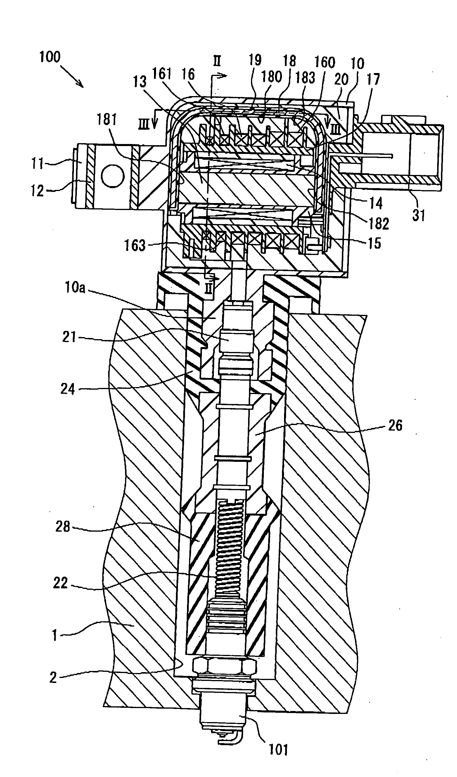
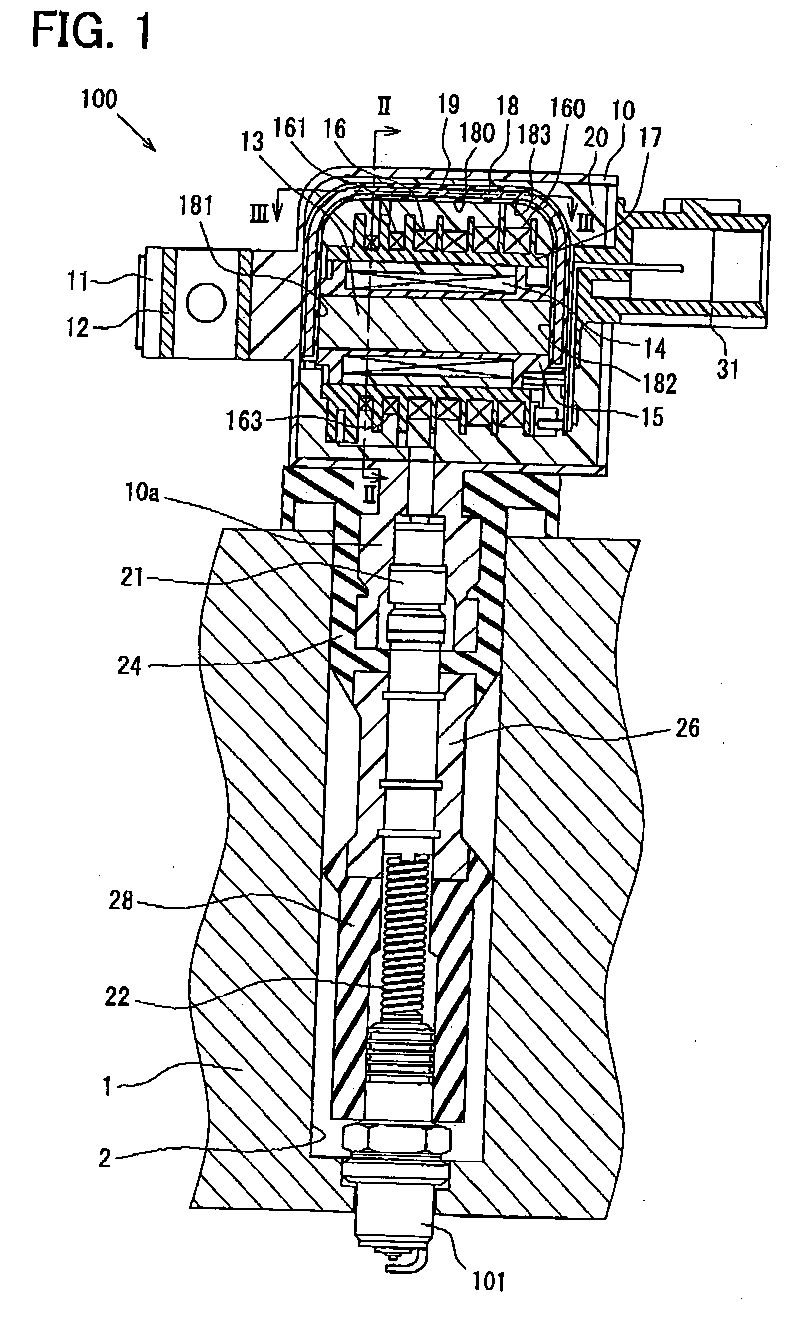
[0050]As shown in FIGS. 1 to 3, a housing 10 is made of a plastic material and formed in a rectangular, boxy shape with a bottom surface larger than a transverse cross section area of a plug hole 2 in an engine head 1. The housing 10 is arranged outside of the plug hole 2. A fixed portion 11 is formed integrally with the housing 10 at an outside thereof. A tubular metal bush 12 is fitted into the fixed portion 11, which is fixed to the engine head 1 by a bolt (not shown) screwed with the metal bush 12.

[0051]It should be noted that the housing 10 and the fixed portion 11 in the present embodiment are made of PBT as a hard resin, but may be made of a thermoplastic resin obtained from condensation polymerization of DMT (dimethyl terephthalate) such as PET and PCT, and 1.4BT (1-4 butanediol) or of a heat-hardening resin such as unsaturated polyester.

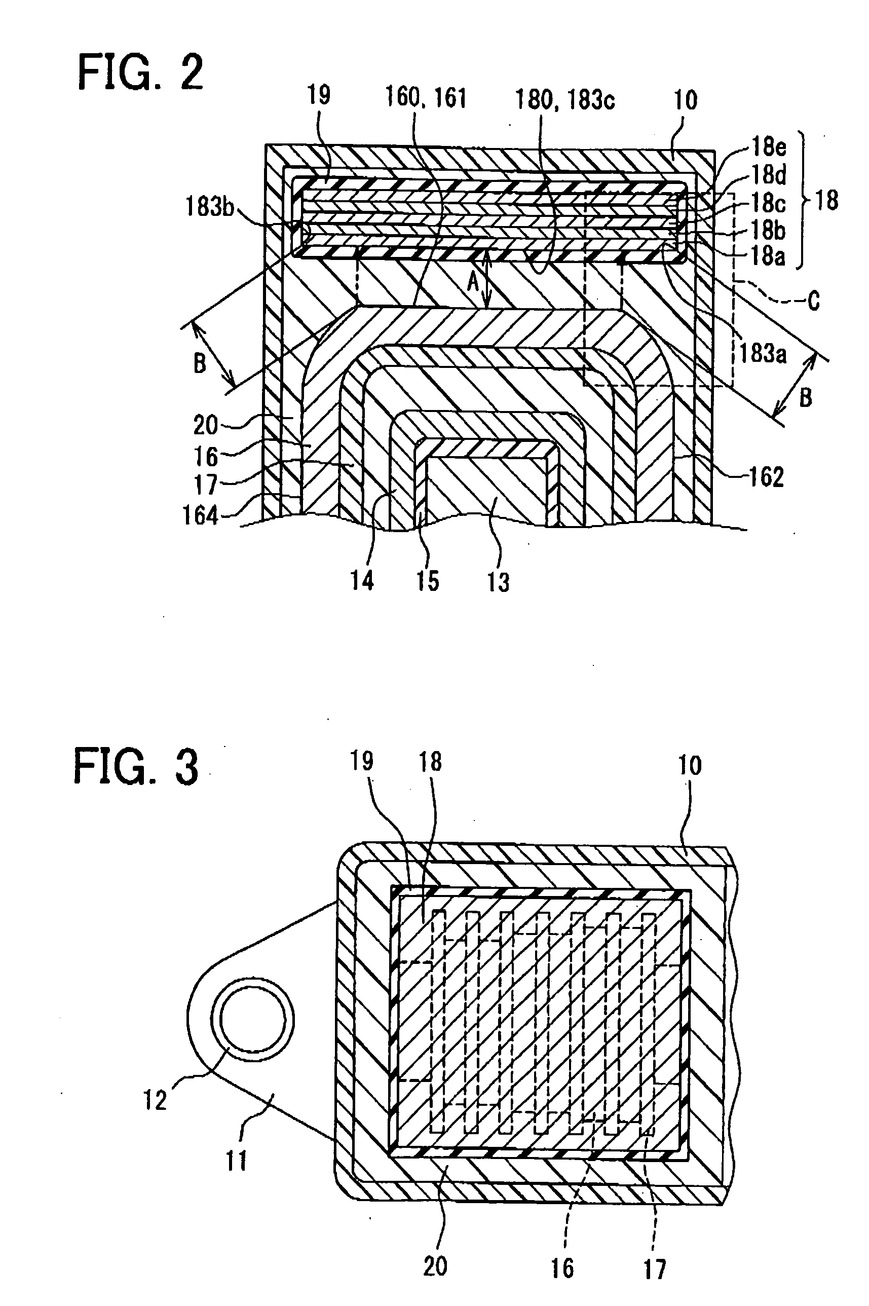
[0052]As shown in FIG. 2, a...

second embodiment

[0089]Hereinafter, the second embodiment will be described, but since the fundamental arrangement thereof is the same as in the first embodiment, different points from the first embodiment only will be explained below.

[0090]FIG. 9 shows a cross section of the ignition coil 100 in its axial direction in the second embodiment. Components corresponding to those in FIG. 2 are referred to as the same numerals. As shown in FIG. 9, a columnar central core 13, a cylindrical secondary coil 16, a cylindrical primary spool 15, a cylindrical primary coil 14 and a cylindrical secondary spool 17 are used. An outer periphery core 18 is formed by pressing magnetic powder, for example, powder of a magnetic metal unit such as iron, cobalt and nickel or an alloy including mainly the metal unit. In consequence, the outer periphery core 18 can be produced less expensively than the one formed by stacking silicon steel plates or the like. By using the cylindrical secondary coil 16, the shortest distance B...

third embodiment

[0101]Hereinafter, the third embodiment will be described, but since the fundamental arrangement thereof is the same as in the above embodiments, only remarkable different points will be explained below.

[0102]FIG. 14 shows a cross section of the ignition coil 100 in its axial direction in the third embodiment. Components corresponding to those in FIG. 2 are referred to as the same numerals as in the case of the second embodiment. As shown in FIG. 14, magnetic plates 18a to 18e each having a different size and a substantially elliptic cross section are used to form an outer periphery core 18, which has a substantially elliptic shape. In this arrangement, outer edges 183a and 183b of an opposing surface 183 in the outer periphery core 18 correspond to points at which the curvature of the opposing surface 183 in a cross section of the outer periphery core 18 perpendicular to an axial direction of a secondary coil 16 changes, more specially, to boundary points between an arc having a re...


PUM

PropertyMeasurementUnit
diameteraaaaaaaaaa
diameteraaaaaaaaaa
voltageaaaaaaaaaa

Abstract

An ignition coil includes a primary coil (14), a secondary coil (16) disposed on an outer circumferential side of the primary coil and configured to be boosted by mutual induction with the primary coil, an outer periphery core (18) having an opposing surface (183), which is opposed to an outer peripheral surface (160) of the secondary coil, and an insulating member (20) disposed between the outer peripheral surface and the opposing surface. The secondary coil and the outer periphery core are arranged such that a shortest distance between the outer peripheral surface and an outer edge (183a, 183b) of the opposing surface is larger than a shortest distance between the outer peripheral surface and the opposing surface.

Description

CROSS REFERENCE TO RELATED APPLICATION[0001]This application is based on and Incorporates herein by reference Japanese Patent Application No. 2007-176547 filed on Jul. 4, 2007, and Japanese Patent Application No. 2008-150465 filed on Jun. 9, 2008.BACKGROUND OF THE INVENTION[0002]1. Field of the Invention[0003]The present invention relates to an ignition coil which generates a voltage applied to an ignition plug for an internal combustion engine.[0004]2. Description of Related Art[0005]There is conventionally known an ignition coil in which a secondary coil arranged at an outer peripheral side of a primary coil is increased in voltage through mutual induction with the primary coil to generate an applied voltage to an ignition plug. There is proposed an ignition coil as one kind of such an ignition coil in which an outer periphery core is arranged in opposition to an outer peripheral surface of the secondary coil and a plastic member is interposed between the secondary coil and the ou...

Claims


Application Information

Patent Timeline
Patent Type & Authority Applications(United States)
IPC IPC(8): H01F38/12H01F27/02
CPCH01F38/12
Inventor WADA, JUNICHI
Owner DENSO CORP
Why Eureka
Try Eureka