Fiber optic cable for very-short-distance networks

a fiber optic cable and very-short-distance technology, applied in the field of fiber optic cables, can solve the problems of cable stiffness, cable is usually not intended for consumer handling, and is usually too stiff to be manually maneuvered in very-short-distance network applications

Active Publication Date: 2013-07-25
CORNING OPTICAL COMM LLC
View PDF7 Cites 28 Cited by
  • Summary
  • Abstract
  • Description
  • Claims
  • Application Information

AI Technical Summary

Benefits of technology

[0007]One embodiment relates to a fiber optic cable that includes a polymeric jacket defining an outer periphery and a cavity interior thereto, an optical fiber positioned within the cavity of the jacket, a first longitudinal strength element fully embedded in the jacket, and a second longitudinal strength element fully embedded in the jacket on an opposite side of the cavity from the first strength longitudinal member. The cavity is elongate. The first and second longitudinal strength elements define a bend axis of the cable passing through the strength elements that is orthogonal to the length of the cable, where the bend axis and the length of the cavity define a preferential plane for bending. The cable resists bending about a third axis that is orthogonal to the length of the cable and also orthogonal to the bend axis, where the third axis and the length of the cable define a non-preferential plane for bending. The cable resists bending in the non-preferential plane by at least twice but no more than five times as much as the cable resists bending in the preferential plane. As such, the difference in flexural rigidity between the preferential and non-preferential planes limits the formation of spontaneous knots in a coil of the cable while still providing flexibility for ease of handling that is commensurate with consumer expectations.

Problems solved by technology

Consumer cables commonly have a round profile without a preferential bend, attributes that are beneficial for making the cables easy to handle, but that also create problems with tangling and spontaneous knot formation of cables.
Such problems may particularly effect small, round-bodied flexible cords, wires, ropes, or cables, because such linear objects, without a preferential bend, generally lack resistance opposing motion once moving radially or perpendicularly to their body-length.
So such cables, when jostled, may undergo random movements that result in spontaneous knot formation.
However, such cables are usually not intended for consumer handling, but instead may be buried underground or aerially supported by telephone poles.
These latter cables are generally too stiff to be manually maneuvered in very-short-distance network applications, such as temporarily connecting a laptop computer and a smart phone for downloads or uploads.
However, the strength elements also pose a danger for attenuating the optical fibers supported by the cables, because bending of the cables off of the preferential bend axis may cause the strength members to move to the neutral axis, pinching or pressuring the optical fibers.
Furthermore, the particularly small size and unconstrained cable movement of some such consumer cables further complicates the process of accessing optical fibers in such cables for attaching connectors or tethers during manufacturing.
For example, it may be difficult to cut a lengthwise slit in a knotted cable of particularly small diameter in order to access optical fibers inside.
As such, attaching connectors or furcating ends of small consumer cables may be difficult as well as time consuming.

Method used


Image

  • Fiber optic cable for very-short-distance networks
  • Fiber optic cable for very-short-distance networks
  • Fiber optic cable for very-short-distance networks

Examples


Embodiment Construction

[0013]Before turning to the following Detailed Description and Figures, which illustrate exemplary embodiments in detail, it should be understood that the present invention is not limited to the details or methodology set forth in the Detailed Description or illustrated in the Figures. For example, as will be understood by those of ordinary skill in the art, features and attributes associated with embodiments shown in one of the Figures or described in the text relating to one of the embodiments may well be applied to other embodiments shown in another of the Figures or described elsewhere in the text.

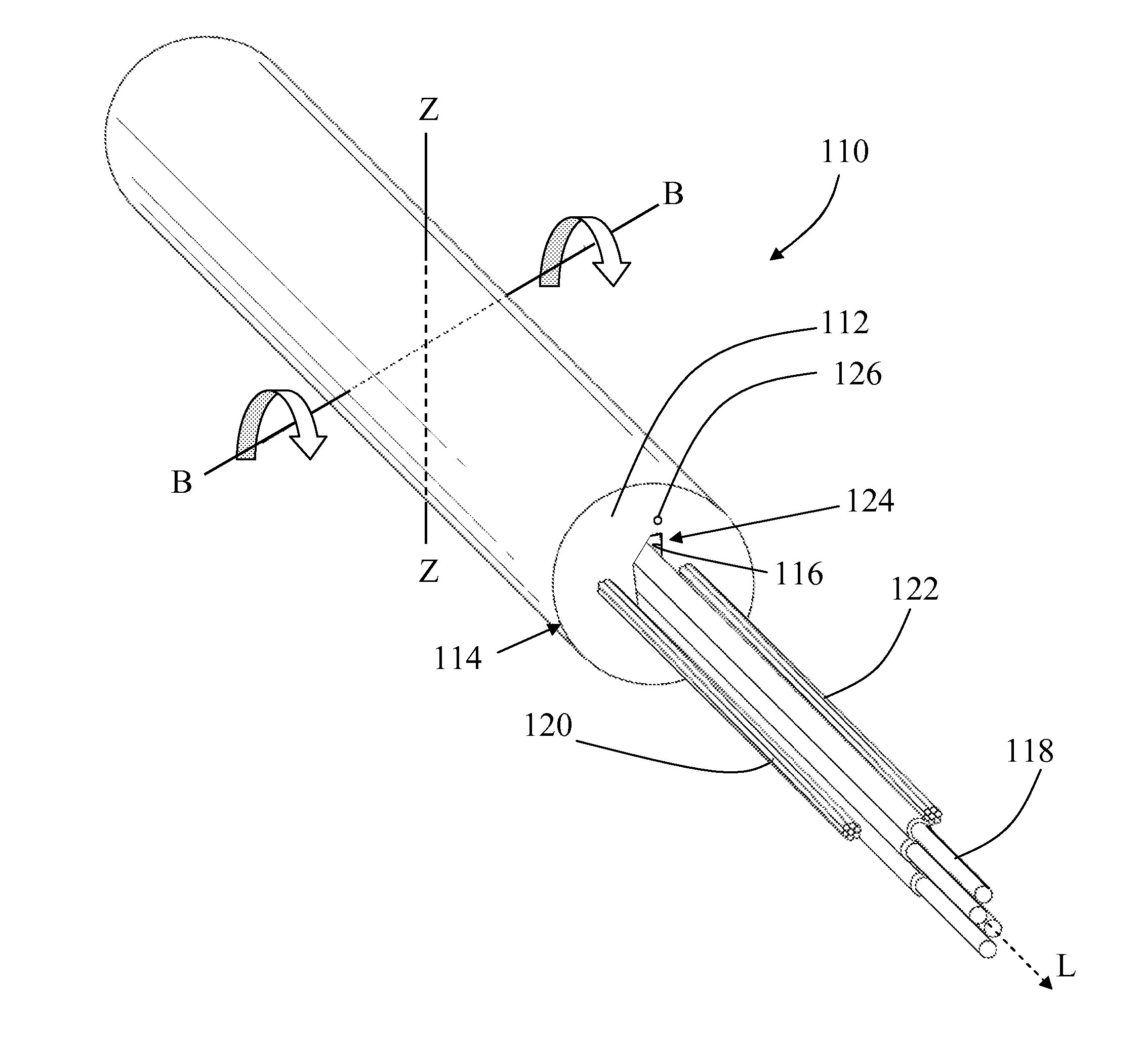
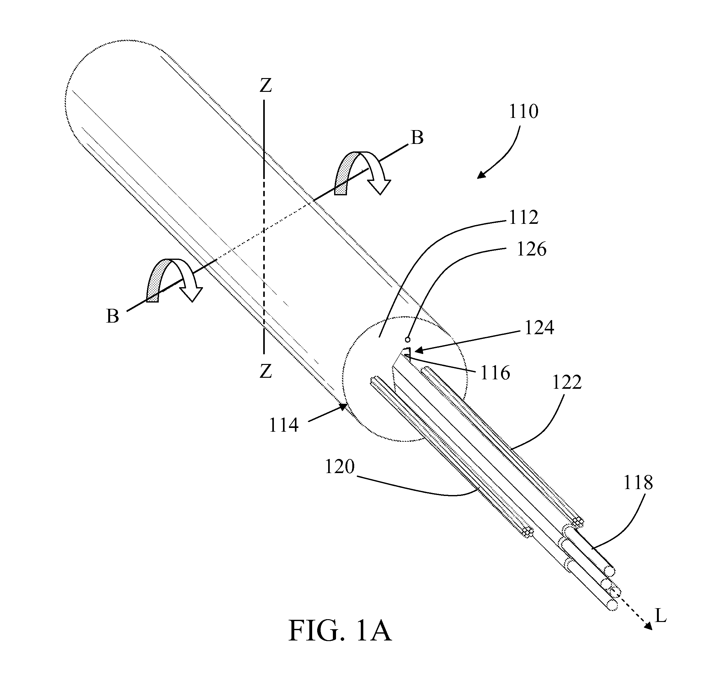
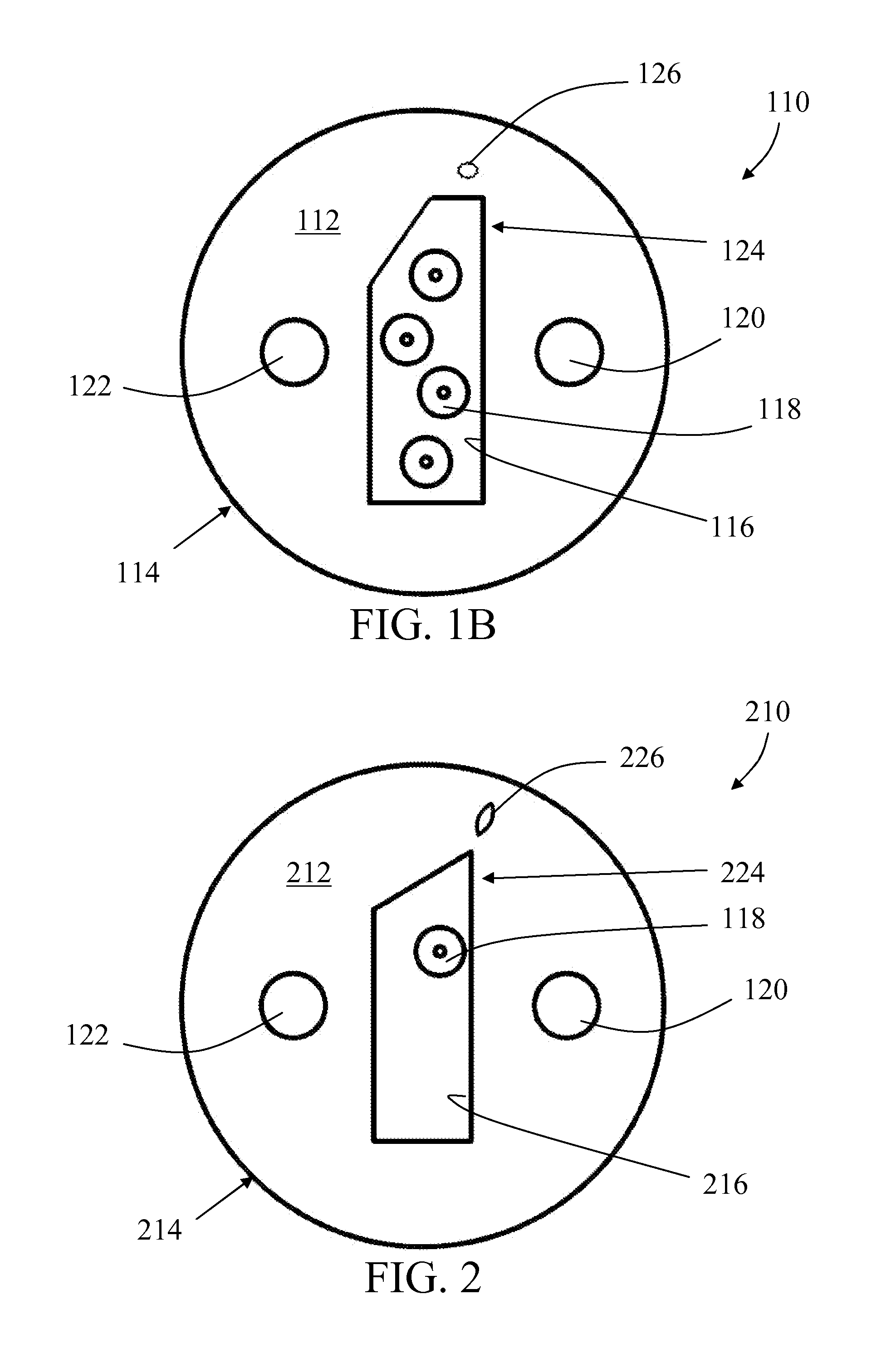
[0014]Referring to FIGS. 1A-1B, a fiber optic cable 110 that includes a polymeric jacket 112 defining an outer periphery 114 and a cavity 116 interior thereto and an optical fiber 118 positioned within the cavity 116 of the jacket 112. The fiber optic cable 110 further includes a first longitudinal strength element 120 fully embedded in the jacket 112, and a second longitudinal strengt...


PUM


Abstract

A fiber optic cable includes a polymeric jacket defining an outer periphery and a cavity interior thereto, an optical fiber positioned within the cavity, and first and second longitudinal strength elements fully embedded in the jacket on opposite sides of the cavity from one another, where the strength elements define a bend axis of the cable passing there through that is orthogonal to the length of the cable, and the bend axis and the length of the cavity define a preferential plane for bending. The cable resists bending about a third axis that is orthogonal to the length of the cable and the bend axis, where the third axis and the length of the cable define a non-preferential plane for bending. The difference in flexural rigidity between the preferential and non-preferential planes limits formation of spontaneous knots in a coil of the cable while providing flexibility for ease of handling.

Description

RELATED CASES[0001]Subject matter disclosed in the present Application is related to subject matter disclosed in U.S. Provisional Application 61 / 588,950 filed Jan. 20, 2012, which is incorporated by reference herein in its entirety.BACKGROUND[0002]Aspects of the present disclosure relate generally to a fiber optic cable configured for use in very-short-distance networks, and particularly configured to facilitate manual handling of the cable and associated hardware due to the size, structure, and bend characteristics of the cable.[0003]Consumer cables commonly have a round profile without a preferential bend, attributes that are beneficial for making the cables easy to handle, but that also create problems with tangling and spontaneous knot formation of cables. Such problems may particularly effect small, round-bodied flexible cords, wires, ropes, or cables, because such linear objects, without a preferential bend, generally lack resistance opposing motion once moving radially or per...

Claims


Application Information

Patent Timeline
Patent Type & Authority Applications(United States)
IPC IPC(8): G02B6/44
CPCG02B6/4403G02B6/4429G02B6/4433G02B6/4206G02B6/4214G02B6/443G02B6/4472
Inventor BRADLEY, MARK ALANMCCOLLOUGH, WILLIAM WELCHREGISTER, III, JAMES ARTHUR
Owner CORNING OPTICAL COMM LLC
Why Eureka
Try Eureka