Vacuum relay

A technology of vacuum relays and vacuum chambers, applied in the direction of relays, electromagnetic relays, detailed information of electromagnetic relays, etc., to achieve the effect of increasing insulation distance and improving voltage resistance

Inactive Publication Date: 2010-09-22
KUNSHAN GUOLI VACUUM ELECTRIC
View PDF0 Cites 4 Cited by
  • Summary
  • Abstract
  • Description
  • Claims
  • Application Information

AI Technical Summary

Problems solved by technology

[0002] At present, the existing vacuum relays on the market are mainly composed of a vacuum chamber, a transmission part and a coil. The voltage resistance of the relay depends not only on the gap between the contacts in the vacuum chamber, but also on the insulation distance between the contact rods outside the vacuum chamber. The side wall section of the vacuum chamber of some relays is mostly circular, square and other shapes. When the maximum outer diameter of the vacuum chamber section is set, the insulation distance between the contact point rods is limited.

Method used


Image

  • Vacuum relay
  • Vacuum relay
  • Vacuum relay

Examples


Embodiment

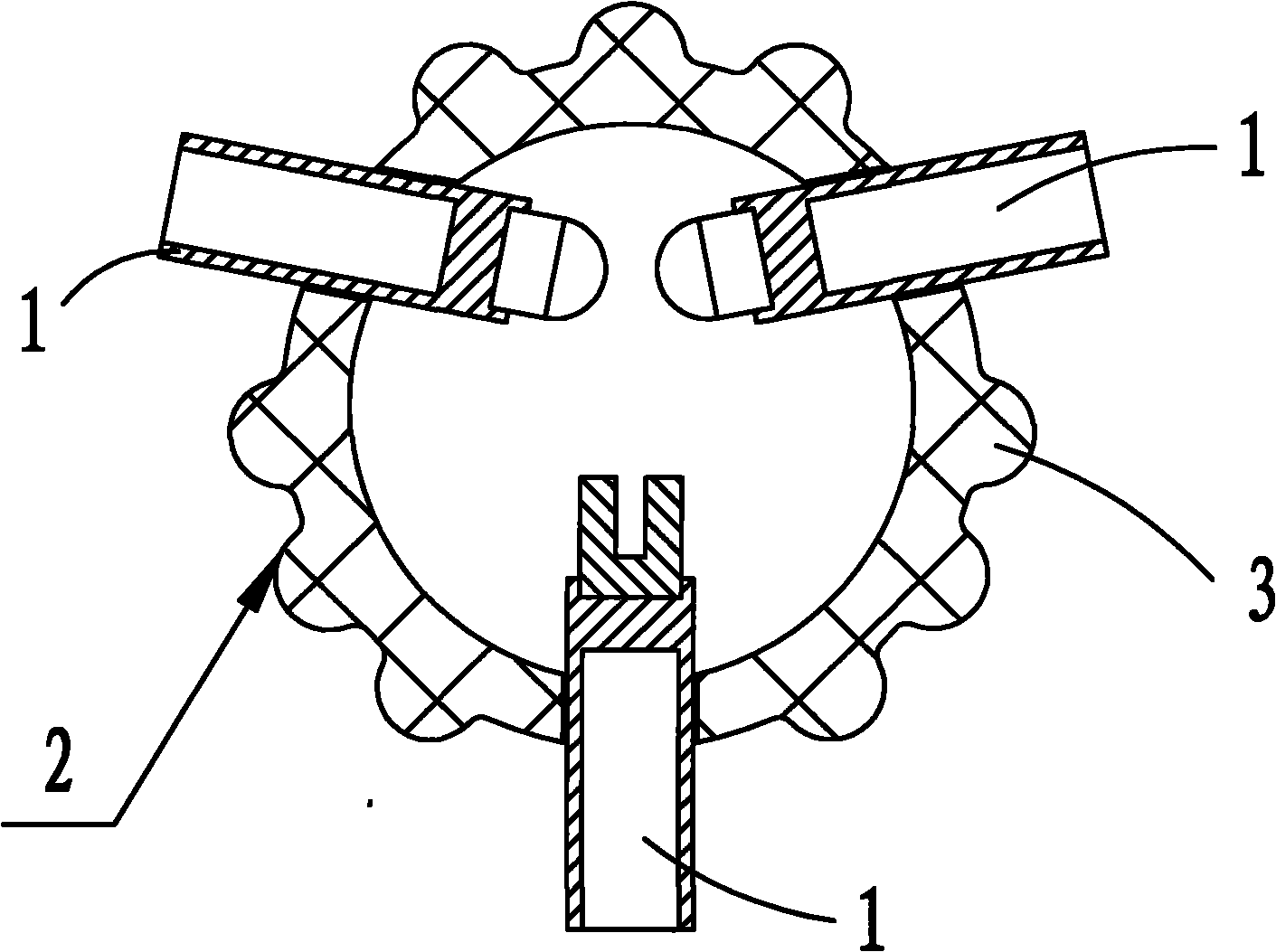
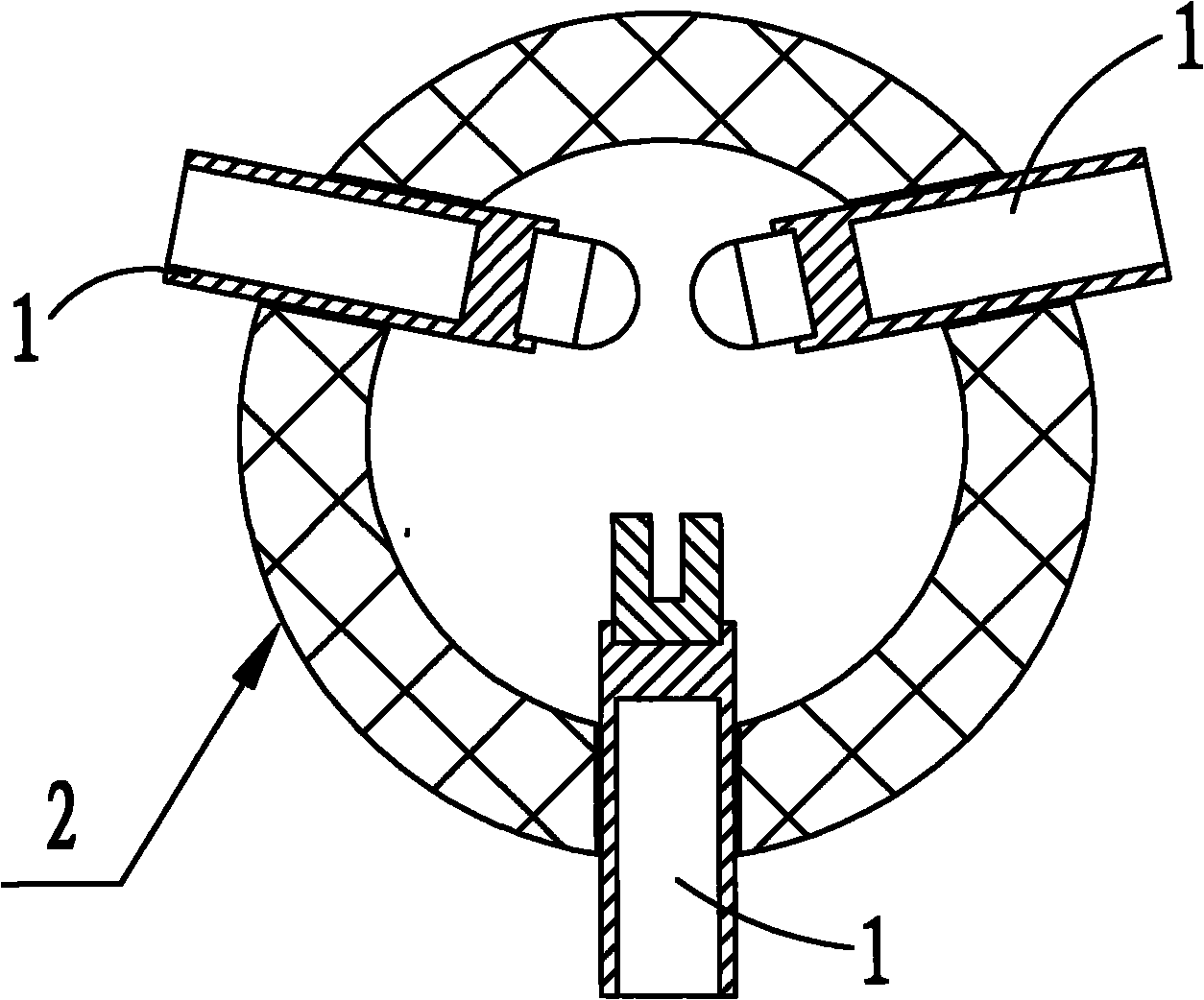
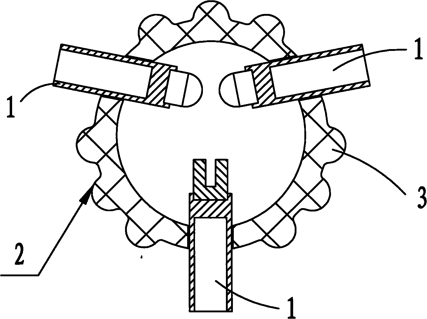
[0010] Embodiment: a vacuum relay, including a vacuum chamber, a number of contact point rods 1 are sealed and installed on the side wall of the vacuum chamber 2, based on the assembly direction, a number of longitudinal The convex rib 3, the outer peripheral section of the side wall of the vacuum chamber 2 between the contact point rods 1 is corrugated.

[0011] Three contact point rods 1 are pierced on the side wall of the vacuum chamber 2 .

[0012] There are three convex ribs 3 on the outside of the side wall of the vacuum chamber 2 between the contact point rods 1 .

[0013] Since some longitudinal convex ribs 3 are formed on the outside of the side wall of the vacuum chamber 2 between the contact point bars 1, the outer peripheral section of the side wall of the vacuum chamber 2 between the contact point bars 1 becomes corrugated, so that the outer contact point of the vacuum chamber 2 The insulation distance between the rods 1 is changed from the original flat arc dist...


PUM


Abstract

The invention discloses a vacuum relay. The vacuum relay comprises a vacuum chamber; a plurality of contact point rods are hermetically inserted in the side wall of the vacuum chamber; based on the assembling direction, the outer side of the side wall of the vacuum chamber among the contact point rods is provided with a plurality of longitudinal protruding ribs; the circumferential section of the side wall of the vacuum chamber among the contact point rods is rippled-shaped, so that the insulation distance among the contact point rods outside the vacuum chamber is changed from the original smooth arc distance or straight line distance to the curve distance, the insulation distance between the two contact point rods is greatly increased, and the voltage withstanding property of the relay is correspondingly greatly improved.

Description

technical field [0001] The invention relates to a relay, especially a vacuum relay. Background technique [0002] At present, the existing vacuum relays on the market are mainly composed of a vacuum chamber, a transmission part and a coil. The voltage resistance of the relay depends not only on the gap between the contacts in the vacuum chamber, but also on the insulation distance between the contact rods outside the vacuum chamber. In some relays, the side wall section of the vacuum chamber is mostly circular, square and other shapes. When the maximum outer diameter of the vacuum chamber section is set, the insulation distance between the contact point rods is limited. Contents of the invention [0003] The technical scheme that the present invention adopts in order to solve its technical problem is: [0004] The vacuum relay includes a vacuum chamber, and several contact point rods are sealed and installed on the side wall of the vacuum chamber. Based on the assembly di...

Claims


Application Information

Patent Timeline
Patent Type & Authority Applications(China)
IPC IPC(8): H01H50/00H01H50/54
Inventor 尹剑平黄浩张立云覃奀壵贾冰冰
Owner KUNSHAN GUOLI VACUUM ELECTRIC
Why Eureka
Try Eureka